Dewalt DWE4517 - User Manual

Dewalt DWE4517 Angle Grinder – User Manual, read for free online in PDF format. We hope this helps you resolve any issues you may have. If you have further questions, please contact us through the contact form.


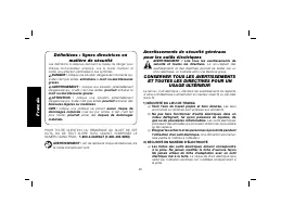
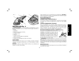
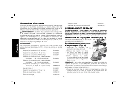
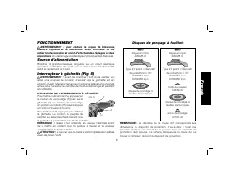
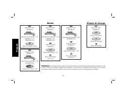
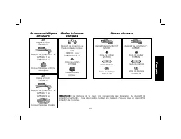
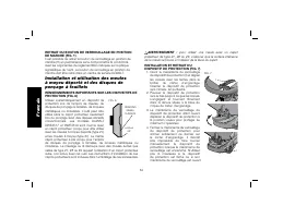
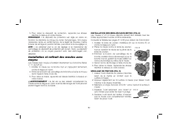
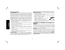
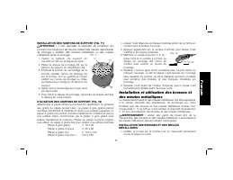
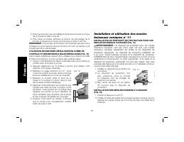
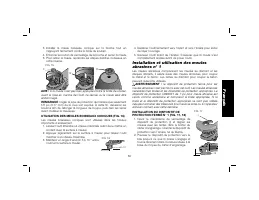
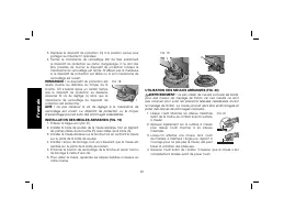
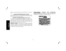


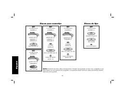


Table of Contents:
- Page 3 – Defi nitions: Safety Guidelines; WALT; General Power Tool Safety Warnings
- Page 4 – ) POWER TOOL USE AND CARE; Keep cutting tools sharp and clean.; English
- Page 8 – Additional Safety Rules for Grinders
- Page 9 – WARNING: Always wear proper personal hearing protection; SAVE THESE INSTRUCTIONS FOR; WALT tools are factory tested if this tool does not; FAMILIARIZATION
- Page 10 – INTENDED USE; use under wet conditions or in presence of flammable; DO NOT; let children come; Features; ROTATING GEAR CASE; The spindle lock pin is provided to prevent the; SOFT MOUNT; Accessories and Attachments; Accessories must be rated for at least the speed
- Page 11 – ATTACHMENTS; ASSEMBLY AND ADJUSTMENTS; OPERATION; WARNING: To reduce the risk of injury, turn unit off
- Page 12 – Power Source; Ensure that the trigger switch is in the off position; TRIGGER OPERATION WITH LOCK-ON FEATURE; Make sure the wheel has come to a complete stop
- Page 13 – Do not tighten the adjusting; Mounting and Removing Hubbed Wheels
- Page 16 – Failure to properly seat the wheel against the soft; EDGE GRINDING WITH GRINDING WHEELS; Wheels used for cutting and edge grinding may break
- Page 17 – Proper guard must be re-installed for grinding wheel,
- Page 18 – MOUNTING WIRE BRUSHES AND WIRE WHEELS; The flaring cup wheel guard is not included with this
- Page 20 – MAINTENANCE; Cleaning
- Page 21 – YEAR FREE SERVICE; XXXXX
- Page 22 – Français
- Page 30 – CONSERVER CES CONSIGNES POUR; WALT sont testés en usine; FAMILIARISATION
- Page 31 – ne jamais modifier l’outil électrique ni aucun; USAGE PRÉVU; Caractéristiques; CARTER D’ENGRENAGES TOURNANT; ne jamais appuyer sur le bouton de commande de; BAGUE EN NYLON
- Page 32 – Accessoires et raccords; la vitesse des accessoires doit correspondre; ACCESSOIRES; ASSEMBLAGE ET RÉGLAGE; AVERTISSEMENT : pour réduire le risque de blessures,
- Page 33 – FONCTIONNEMENT; Source d’alimentation; avant de brancher l’outil sur le secteur ou; UTILISATION DE L’INTERRUPTEUR À GÂCHETTE; s’assurer que la meule s’est complètement arrêtée; Disques de ponçage à feuillets
- Page 36 – ponçage à feuillets; pour utiliser une meule avec un capot
- Page 38 – MEULAGE DE BORDURE; au cours du meulage ou de la coupe de bord,; FINITION DE SURFACE À L’AIDE DE DISQUES DE PONÇAGE; Installation et utilisation des tampons de; Installation
- Page 40 – INSTALLATION DES MEULES BOISSEAUX CONIQUES
- Page 43 – Nettoyage
- Page 45 – Defi niciones: Normas de seguridad; WALT, LLÁMENOS AL NÚMERO; CONSERVE TODAS LAS ADVERTENCIAS; ) SEGURIDAD EN EL ÁREA DE TRABAJO; Español
- Page 52 – SIEMPRE
- Page 54 – USO DEBIDO; Características; CAJA DE ENGRANES GIRATORIA; no presione el botón de cierre del huso mientras el; MONTAJE SUAVE; Accesorios y dispositivos; los accesorios deben estar clasificados por lo; DISPOSITIVOS
- Page 55 – ENSAMBLAJE Y AJUSTES; ADVERTENCIA: Para reducir el riesgo de lesiones personales; Sanding Flap Discs
- Page 58 – OPERACIÓN; Alimentación de corriente; OPERACIÓN DEL GATILLO; Para encender la herramienta, presione el
- Page 60 – ESMERILADO DE BORDES CON DISCOS DE ESMERILAR; Los discos usados para el corte y esmerilado de
- Page 61 – Instalación y utilización de las para lijar; Después de utilizar la
- Page 62 – INSTALACIÓN DE COPAS Y DISCOS DE ALAMBRE; La guarda para piedras de viene incluida con
- Page 64 – MANTENIMIENTO; Limpieza; Sople la suciedad y el polvo de todos los
- Page 65 – Nunca utilice solventes ni otros químicos; Accesorios; Debido a que no se han probado con este; Reparaciones; WALT, en un centro de mantenimiento; PARA REPARACIÓN Y SERVICIO DE SUS HERRAMIENTAS
- Page 66 – Póliza de Garantía; EXCEPCIONES; Garantía limitada por tres años; AÑO DE SERVICIO GRATUITO
- Page 67 – ESPECIFICACIONES
- Page 68 – OPTIMAL
DWE4517, DWE4519
Heavy-Duty Large Angle Grinders
Grandes rectifieuses coudées de service intensif
Esmeriladoras de ángulo grande para trabajo pesado
INSTRUCTION MANUAL
GUIDE D’UTILISATION
MANUAL DE INSTRUCCIONES
INSTRUCTIVO DE OPERACIÓN, CENTROS DE SERVICIO Y PÓLIZA DE
GARANTÍA.
ADVERTENCIA:
LÉASE ESTE INSTRUCTIVO ANTES DE
USAR EL PRODUCTO.
If you have questions or comments, contact us.
Pour toute question ou tout commentaire, nous contacter.
Si tiene dudas o comentarios, contáctenos.
1-800-4-D
E
WALT • www.dewalt.com
"Loading the manual" means you need to wait until the file loads and becomes available for online reading. Some manuals are very large, and the time they take to appear depends on your internet speed.
Other Manuals for Dewalt DWE4517
Summary
Defi nitions: Safety Guidelines The definitions below describe the level of severity for each signal word. Please read the manual and pay attention to these symbols. DANGER: Indicates an imminently hazardous situation which, if not avoided, will result in death or serious injury . WARNING: Indicates ...
3) PERSONAL SAFETY a) Stay alert, watch what you are doing and use common sense when operating a power tool. Do not use a power tool while you are tired or under the influence of drugs, alcohol or medication. A moment of inattention while operating power tools may result in serious personal injury. ...
Safety Warnings Specifi c for Wire Brushing Operations a) Be aware that wire bristles are thrown by the brush even during ordinary operation. Do not overstress the wires by applying excessive load to the brush. The wire bristles can easily penetrate light clothing and/or skin. b) If the use of a guar...