Page 7 - Safety instructions; Before working inside your computer
Working on your computer Safety instructions Use the following safety guidelines to protect your computer from potential damage and to ensure your personal safety. Unless otherwisenoted, each procedure included in this document assumes that the following conditions exist: • You have read the safety ...
Page 8 - Safety precautions; Standby power; Electrostatic discharge—ESD protection
Safety precautions The safety precautions chapter details the primary steps to be taken before performing any disassembly instructions. Observe the following safety precautions before you perform any installation or break/fix procedures involving disassembly or reassembly: • Turn off the system and ...
Page 9 - ESD field service kit; Components of an ESD field service kit; ESD protection summary; Transporting sensitive components; Lifting equipment
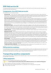
ESD field service kit The unmonitored Field Service kit is the most commonly used service kit. Each Field Service kit includes three main components: anti-static mat, wrist strap, and bonding wire. Components of an ESD field service kit The components of an ESD field service kit are: • Anti-Static M...
Page 10 - After working inside your computer
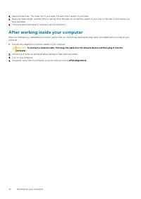
4. Keep the load close. The closer it is to your spine, the less force it exerts on your back.5. Keep your back upright, whether lifting or setting down the load. Do not add the weight of your body to the load. Avoid twisting your body and back. 6. Follow the same techniques in reverse to set the lo...
Page 11 - Technology and components; DDR4 Details
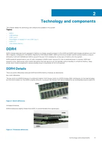
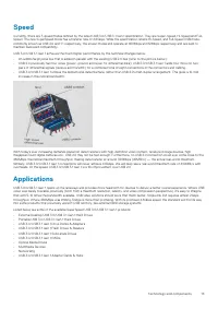
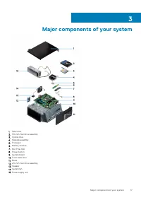
Technology and components This chapter details the technology and components available in the system. Topics: • DDR4 • USB features • USB Type-C • Advantages of DisplayPort over USB Type-C • HDMI 2.0 • Intel Optane memory DDR4 DDR4 (double data rate fourth generation) memory is a higher-speed succes...
Page 12 - Memory Errors
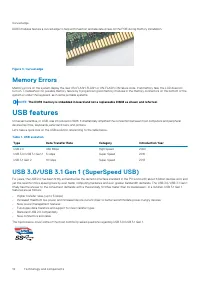
Curved edge DDR4 modules feature a curved edge to help with insertion and alleviate stress on the PCB during memory installation. Figure 3. Curved edge Memory Errors Memory errors on the system display the new ON-FLASH-FLASH or ON-FLASH-ON failure code. If all memory fails, the LCD does notturn on. ...
Page 14 - Advantages of DisplayPort over USB Type-C
Compatibility The good news is that USB 3.0/USB 3.1 Gen 1 has been carefully planned from the start to peacefully co-exist with USB 2.0. First of all,while USB 3.0/USB 3.1 Gen 1 specifies new physical connections and thus new cables to take advantage of the higher speed capability ofthe new protocol...
Page 15 - Advantages of HDMI; Intel Optane memory
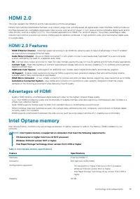
HDMI 2.0 This topic explains the HDMI 2.0 and its features along with the advantages. HDMI (High-Definition Multimedia Interface) is an industry-supported, uncompressed, all-digital audio/video interface. HDMI provides aninterface between any compatible digital audio/video source, such as a DVD play...
Page 19 - Side cover; Removing side cover; Installing side cover
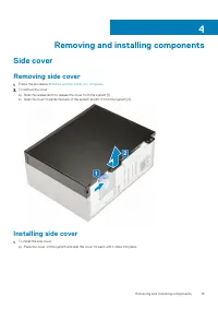
Removing and installing components Side cover Removing side cover 1. Follow the procedure in Before working inside your computer . 2. To remove the cover: a) Slide the release latch to release the cover from the system [1].b) Slide the cover towards the back of the system and lift it from the system...
Page 20 - Bezel; Removing front bezel
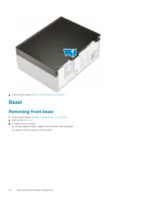
2. Follow the procedure in After working inside your computer . Bezel Removing front bezel 1. Follow the procedure in Before working inside your computer . 2. Remove the Side cover . 3. To remove the front bezel: a) Pry the retention tabs to release the front bezel from the system.b) Remove the fron...
Page 21 - Installing front bezel
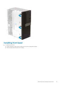
Installing front bezel 1. To install the front bezel: a) Position the bezel to align the tab holders with the slots on the system chassis.b) Press the bezel until the tabs click into place. Removing and installing components 21
Page 22 - Front panel door; Opening front panel door
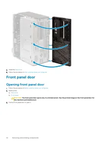
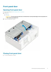
2. Install the Side cover . 3. Follow the procedure in After working inside your computer . Front panel door Opening front panel door 1. Follow the procedure in Before working inside your computer . 2. Remove the: a) Side cover b) Front bezel CAUTION: The front panel door opens only to a limited ext...
Page 23 - Closing front panel door
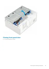
Closing front panel door 1. Turn the front panel door to close it. Removing and installing components 23
Page 24 - Removing 3.5–inch hard drive assembly
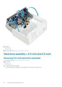
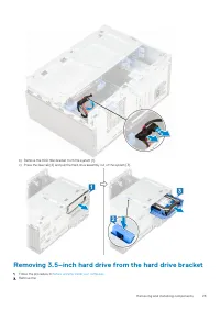
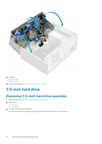
2. Install the: a) Front bezel b) Side cover 3. Follow the procedure in After working inside your computer . Hard drive assembly—3.5-inch and 2.5-inch Removing 3.5–inch hard drive assembly 1. Follow the procedure in Before working inside your computer . 2. Remove the: a) Side cover b) Front bezel 3....
Page 25 - Removing 3.5–inch hard drive from the hard drive bracket
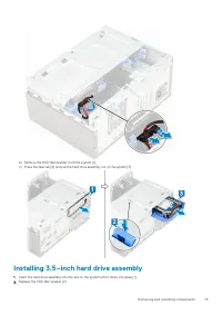
b) Remove the HDD filler bracket from the system [1].c) Press the blue tab [2] and pull the hard drive assembly out of the system [3]. Removing 3.5–inch hard drive from the hard drive bracket 1. Follow the procedure in Before working inside your computer . 2. Remove the: Removing and installing comp...
Page 26 - Installing 3.5–inch hard drive assembly
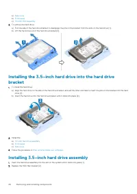
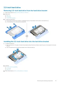
a) Side cover b) Front bezel c) 3.5-inch HDD assembly 3. To remove the hard drive : a) Pull one side of the hard drive bracket to disengage the pins on the bracket from the slots on the hard drive [1].b) Lift the hard drive out of the hard drive bracket [2]. Installing the 3.5–inch hard drive into t...
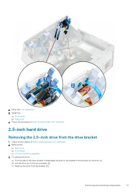
Page 28 - Removing the 2.5–inch hard drive assembly; Removing the 2.5–inch drive from the drive bracket
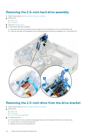
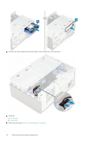
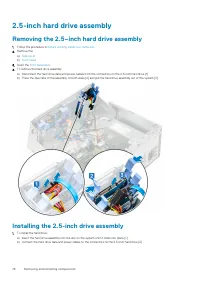
Removing the 2.5–inch hard drive assembly 1. Follow the procedure in Before working inside your computer . 2. Remove the: a) Side cover b) Front bezel 3. Open the front panel door . 4. To remove the hard drive assembly: a) Disconnect the hard drive data and power cables from the connectors on the 2....
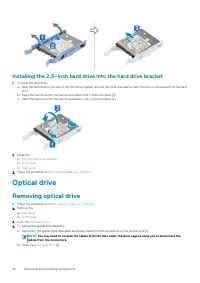
Page 30 - Optical drive; Removing optical drive
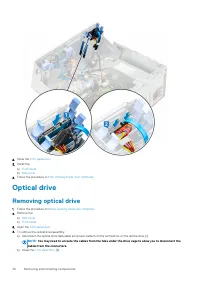
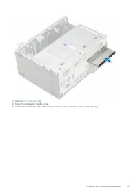
2. Close the front panel door . 3. Install the: a) Front bezel b) Side cover 4. Follow the procedure in After Working Inside Your Computer . Optical drive Removing optical drive 1. Follow the procedure in Before working inside your computer . 2. Remove the: a) Side cover b) Front bezel 3. Open the f...
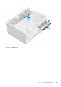
Page 32 - Installing optical drive
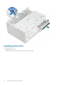
Installing optical drive 1. To install the optical drive: a) Close the front panel door . b) Insert the optical drive into the optical drive bay until it clicks into place. 32 Removing and installing components
Page 36 - SD card reader; Removing SD card reader
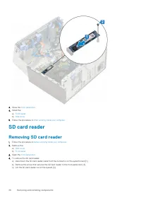
3. Close the front panel door . 4. Install the: a) Front bezel b) Side cover 5. Follow the procedure in After working inside your computer . SD card reader Removing SD card reader 1. Follow the procedure in Before working inside your computer . 2. Remove the: a) Side cover b) Front bezel 3. Open the...
Page 37 - Installing SD card reader
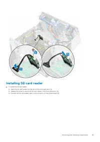
Installing SD card reader 1. To install the SD card reader: a) Insert the SD card reader into the slot on the front panel door [1].b) Replace the screw to secure the SD card reader to the front panel door [2].c) Connect the SD card reader cable to the connector on the system board [3]. Removing and ...
Page 38 - Memory module; Removing memory module
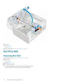
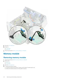
2. Close the front panel door . 3. Install the: a) Front bezel b) Side cover 4. Follow the procedure in After working inside your computer . Memory module Removing memory module 1. Follow the procedure in Before working inside your computer . 2. Remove the: a) Side cover b) Front bezel 3. Open the f...
Page 39 - Installing memory module
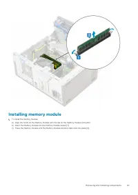
Installing memory module 1. To install the memory module: a) Align the notch on the memory module with the tab on the memory module connector.b) Insert the memory module into the memory module socket [1].c) Press the memory module until the memory module retention tabs click into place [2]. Removing...
Page 40 - Expansion card; Removing PCIe expansion card
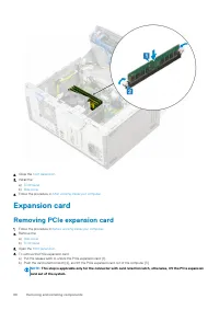
2. Close the front panel door . 3. Install the: a) Front bezel b) Side cover 4. Follow the procedure in After working inside your computer . Expansion card Removing PCIe expansion card 1. Follow the procedure in Before working inside your computer . 2. Remove the: a) Side cover b) Front bezel 3. Ope...
Page 41 - Installing PCIe expansion card
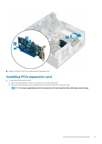
5. Repeat the steps to remove any additional PCIe expansion card. Installing PCIe expansion card 1. To install the PCIe expansion card: a) Insert the PCIe expansion card to the connector on the system board [1].b) Secure the PCIe expansion card by pushing the card retention latch until it clicks int...
Page 42 - Optional VGA module; Removing optional VGA module
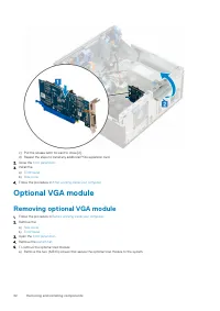
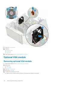
c) Pull the release latch forward to close [2].d) Repeat the steps to install any additional PCIe expansion card. 2. Close the front panel door . 3. Install the: a) Front bezel b) Side cover 4. Follow the procedure in After working inside your computer . Optional VGA module Removing optional VGA mod...
Page 43 - Installing optional VGA module
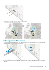
b) Disconnect the VGA cable from the connector on the system board [1].c) Remove the VGA module from the system [2]. Installing optional VGA module 1. To remove the metal bracket as shown below, insert a flathead screwdriver in the hole of the bracket [1], push the bracket to release the bracket [2]...
Page 44 - Power supply unit; Removing power supply unit or PSU
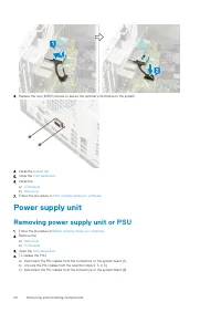
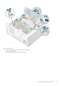
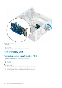
3. Replace the two (M3X3) screws to secure the optional VGA module to the system. 4. Install the system fan . 5. Close the front panel door . 6. Install the: a) Front bezel b) Side cover 7. Follow the procedure in After working inside your computer . Power supply unit Removing power supply unit or P...
Page 46 - Installing power supply unit or PSU
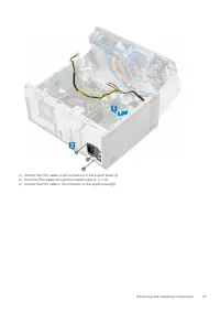
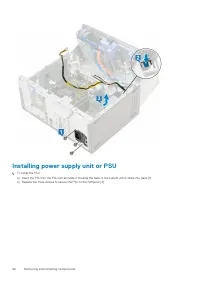
Installing power supply unit or PSU 1. To install the PSU: a) Insert the PSU into the PSU slot and slide it towards the back of the system until it clicks into place [1].b) Replace the three screws to secure the PSU to the computer [2] . 46 Removing and installing components
Page 48 - Intrusion switch; Removing intrusion switch
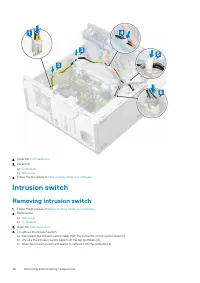
2. Close the front panel door . 3. Install the: a) Front bezel b) Side cover 4. Follow the procedure in After working inside your computer . Intrusion switch Removing intrusion switch 1. Follow the procedure in Before working inside your computer . 2. Remove the: a) Side cover b) Front bezel 3. Open...
Page 49 - Installing intrusion switch
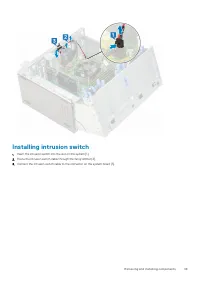
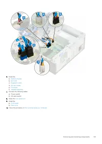
Installing intrusion switch 1. Insert the intrusion switch into the slot on the system [1].2. Route the intrusion switch cable through the fan grommet [2].3. Connect the intrusion switch cable to the connector on the system board [3]. Removing and installing components 49
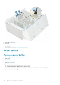
Page 50 - Power button; Removing power button
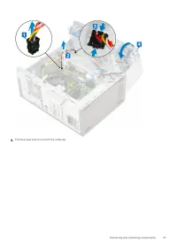
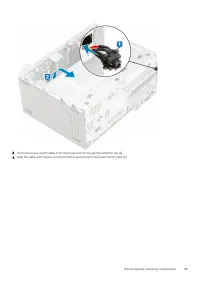
4. Close the front panel door . 5. Install the: a) Front bezel b) Side cover 6. Follow the procedure in After working inside your computer . Power button Removing power button 1. Follow the procedure in Before working inside your computer . 2. Remove the: a) Side cover b) Front bezel 3. Open the fro...
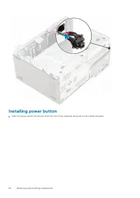
Page 52 - Installing power button
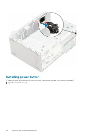
Installing power button 1. Insert the power switch into the slot from the front of the computer and press it until it clicks into place. 52 Removing and installing components
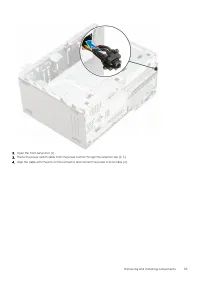
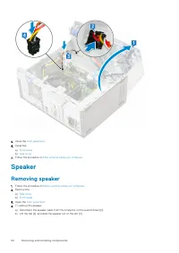
Page 54 - Speaker; Removing speaker
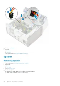
5. Close the front panel door . 6. Install the: a) Front bezel b) Side cover 7. Follow the procedure in After working inside your computer . Speaker Removing speaker 1. Follow the procedure in Before working inside your computer . 2. Remove the: a) Side cover b) Front bezel 3. Open the front panel d...
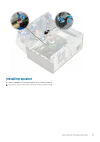
Page 55 - Installing speaker
Installing speaker 1. Insert the speaker into the slot and press it until it clicks into place [1].2. Connect the speaker cable to the connector on the system board [2]. Removing and installing components 55
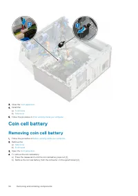
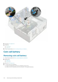
Page 56 - Coin cell battery; Removing coin cell battery
3. Close the front panel door . 4. Install the: a) Front bezel b) Side cover 5. Follow the procedure in After working inside your computer . Coin cell battery Removing coin cell battery 1. Follow the procedure in Before working inside your computer . 2. Remove the: a) Side cover b) Front bezel 3. Op...
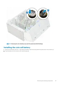
Page 57 - Installing the coin cell battery
NOTE: Removing the coin cell battery may reset the system board BIOS/Settings Installing the coin cell battery 1. Hold the coin cell battery with the "+" sign facing up and slide it under the securing tabs at the positive side of the connector [1].2. Press the battery into the connector unti...
Page 58 - Heat sink fan; Removing heat sink fan
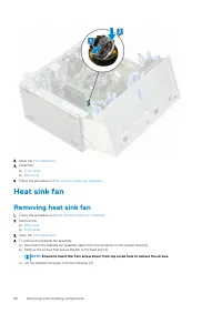
3. Close the front panel door . 4. Install the: a) Front bezel b) Side cover 5. Follow the procedure in After working inside your computer . Heat sink fan Removing heat sink fan 1. Follow the procedure in Before working inside your computer . 2. Remove the: a) Side cover b) Front bezel 3. Open the f...
Page 59 - Installing heatsink fan
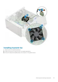
Installing heatsink fan 1. Place the fan on the heatsink assembly [1].2. Tighten the screws (4) to secure the fan to the heatsink assembly [2].3. Connect the heatsink fan assembly cable to the connector on the system board [3]. Removing and installing components 59
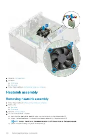
Page 60 - Heat sink; Removing heatsink assembly
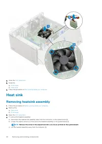
4. Close the front panel door . 5. Install the: a) Front bezel b) Side cover 6. Follow the procedure in After working inside your computer . Heat sink Removing heatsink assembly 1. Follow the procedure in Before working inside your computer . 2. Remove the: a) Side cover b) Front bezel 3. Open the f...
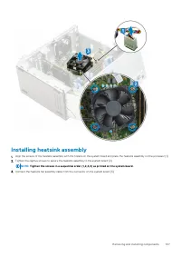
Page 61 - Installing heatsink assembly
Installing heatsink assembly 1. Align the screws of the heatsink assembly with the holders on the system board and place the heatsink assembly on the processor [1].2. Tighten the captive screws to secure the heatsink assembly to the system board [2]. NOTE: Tighten the screws in a sequential order (1...
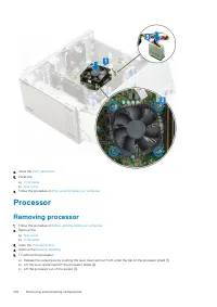
Page 62 - Processor; Removing processor
4. Close the front panel door . 5. Install the: a) Front bezel b) Side cover 6. Follow the procedure in After working inside your computer . Processor Removing processor 1. Follow the procedure in Before working inside your computer . 2. Remove the: a) Side cover b) Front bezel 3. Open the front pan...
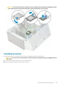
Page 63 - Installing processor
CAUTION: Do not touch the processor socket pins, they are fragile and can be permanently damaged. Be careful not to bend the pins in the processor socket when removing the processor out of the socket. Installing processor 1. Place the processor on the socket such that the slots on the processor alig...
Page 64 - System fan; Removing system fan
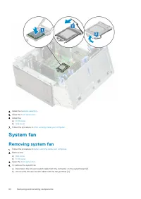
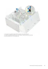
4. Install the heatsink assembly . 5. Close the front panel door . 6. Install the: a) Front bezel b) Side cover 7. Follow the procedure in After working inside your computer . System fan Removing system fan 1. Follow the procedure in Before working inside your computer . 2. Remove the: a) Side cover...
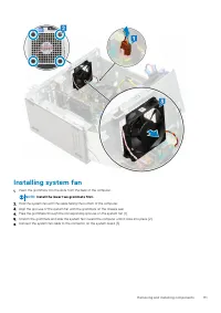
Page 66 - Installing system fan
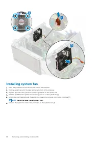
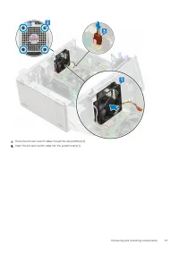
Installing system fan 1. Insert the grommets into the slots on the back of the computer.2. Hold the system fan with the cable facing the bottom of the computer.3. Align the grooves of the system fan with the grommets on the chassis wall.4. Pass the grommets through the corresponding grooves on the s...
Page 68 - System board; Removing system board
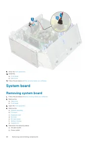
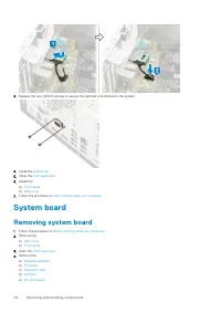
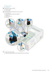
9. Close the front panel door . 10. Install the: a) Front bezel b) Side cover 11. Follow the procedure in After working inside your computer . System board Removing system board 1. Follow the procedure in Before working inside your computer . 2. Remove the: a) Side cover b) Front bezel 3. Open the f...
Page 75 - Installing the 3.5–inch hard drive into the hard drive bracket
3.5-inch hard drive Removing 3.5–inch hard drive from the hard drive bracket 1. Follow the procedure in Before working inside your computer . 2. Remove the: a) Side cover b) Front bezel c) 3.5-inch HDD assembly 3. To remove the hard drive : a) Pull one side of the hard drive bracket to disengage the...
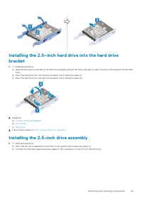
Page 78 - Installing the 2.5–inch hard drive into the hard drive bracket
Installing the 2.5–inch hard drive into the hard drive bracket 1. To install the hard drive: a) Align the hard drive to the side of the hard drive bracket, and pull the other end tabs to insert the pins on the bracket into the hard drive. b) Insert the hard drive into the hard drive bracket until it...
Page 106 - Heatsink assembly
4. Close the front panel door . 5. Install the: a) Front bezel b) Side cover 6. Follow the procedure in After working inside your computer . Heatsink assembly Removing heatsink assembly 1. Follow the procedure in Before working inside your computer . 2. Remove the: a) Side cover b) Front bezel 3. Op...
Page 117 - Installing the system board
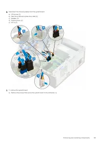
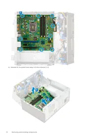
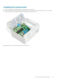
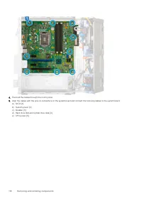
Installing the system board 1. Hold the system board by its edges and align it towards the back of the computer.2. Lower the system board into the computer until the connectors at the back of the system board align with the slots on the chassis, and the screw holes on the system board align with the...
Page 120 - Troubleshooting; Running the ePSA Diagnostics; Diagnostics
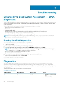
Troubleshooting Enhanced Pre-Boot System Assessment — ePSAdiagnostics The ePSA diagnostics (also known as system diagnostics) performs a complete check of your hardware. The ePSA is embedded with theBIOS and is launched by the BIOS internally. The embedded system diagnostics provides a set of option...
Page 122 - Diagnostic error messages
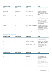
Amber LED state White LED state System state Notes device config or failure withvideo sub sytem config or failure.BIOS to eliminate 0101 videocode. 3 2 BIOS state 5 BIOS Post code (Old LEDpattern 0110) Combine storageand USB config or failure. BIOSto eliminate 0111 USB code. 3 3 BIOS state 6 BIOS Po...
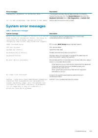
Page 125 - System error messages
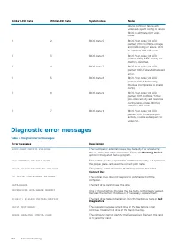
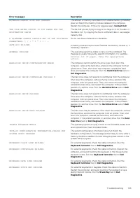
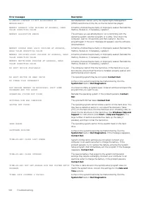
Error messages Description UNEXPECTED INTERRUPT IN PROTECTED MODE The keyboard controller may be malfunctioning, or a memorymodule may be loose. Run the System Memory tests and the Keyboard Controller test in Dell Diagnostics or Contact Dell . X:\ IS NOT ACCESSIBLE. THE DEVICE IS NOT READY Insert a ...


 Dell (L521X, User Manual
 Dell 0K027RA00 Manual
 Dell 1 Manual
 Dell 1.8 Manual
 Dell 2 Manual
 Dell 3 Manual
 Dell 4.4 Manual
 Dell 4J182 Manual
 Dell 6 Manual
 Dell 7 Manual
 Dell 7.4 Manual
 Dell 7.6 Manual
 Dell 8 Manual
 Dell 8.1 Manual
 Dell 9H825 Manual
 Dell 10 Manual
 Dell 10 Pro User Manual
 Dell 11 User Manual
 Dell 11 Pro User Manual