Crest LCD009 - User Manual
Crest LCD009 TV Bracket – User Manual, read for free online in PDF format. We hope this helps you resolve any issues you may have. If you have further questions, please contact us through the contact form.

Part 3 – Slide the Pieces Together
1. Carefully slide the mount with your LCD attached into the wall piece (see Diagram
3a).
2. For additional security, screw the wall piece and mount together using two (2) of the
M4 x 12 Bolts (C) and a long screw driver (see Diagram 3b).
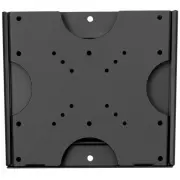
Part 2 – Attach the Mount To Your Display
1. Determine which hardware to use by examining the back of your display. If your
display has a flat back, you will use one of the shorter bolts (C or D). If your display has a
curved or recessed back, you will use one of the longer bolts (E or F) along with one of
the spacers (G or H). Use the diameter bolt that best fits your particular display.
2. Attach the mount to the back of your display (see Diagram 2) using the holes that
match the pattern on the back of your display.
Diagram 3b
Display
M4 x 12 Bolt (C)
Installed Wall Piece
Display
Diagram 3a
Warnings
1. Carefully read these instructions before beginning your installation. If you are
unsure of any part of this installation, contact a professional installer for assistance.
2. The wall or mounting surface must be capable of supporting the combined
weight of the mount and the display; otherwise the structure must be reinforced.
3. Safety gear and proper tools must be used. Failure to do so may result in damage
or injury.
4. Follow your display manufacturer’s recommendations regarding adequate
ventilation and suitable mounting locations. Consult your owner‘s manual for more
information.
Required Tools
Hardware
Installation
Check to make sure all hardware has been included with your mount. You should find
the following:
Part 1a – Install the Wall Piece (Drywall)
1. Using a high quality stud finder, locate and mark one stud for installing the wall
mount.
2. Place the wall piece against the wall over the center of the marked stud and make
sure it is level.
3. Mark off the two holes in the center of the mount and place the wall piece aside.
4. Drill the marked holes using an electric drill and 1/8” bit.
5. Replace the wall piece against the wall and secure it using two (2) Drywall Screws (A)
from the hardware kit (see Diagram 1a).
Part 1b – Install the Wall Piece (Concrete)
1. Place the wall piece against the wall in the desired location and make sure it is level.
2. Mark off four holes (one at each corner) for securing the mount and place the wall
piece aside.
3. Drill the marked holes using an electric drill and 5/16” masonry bit. Remove any
excess dust from the holes after drilling.
4. Insert a Concrete Anchor (B) into each hole. A hammer can be used to lightly tap
each anchor into place if necessary.
5. Replace the wall piece against the wall and secure it using four (4) Drywall Screws (A)
from the hardware kit (see Diagram 1b).
Diagram 1a
Diagram 1b
Drywall
Screw (A)
Wall Piece
You will need the following tools to complete your installation:
• Phillips Head Screw Driver
• Electric or Portable Drill
• Stud Finder and 1/8” Drill Bit for Drywall Installation
• 5/16” Masonry Bit for Concrete Installation
(A) Drywall Screw x4
(B) Concrete Anchor x4
(C) M4 x 12 Bolt x6
(E) M4 x 30 Bolt x4
(G) Small Spacer x4
(F) M6 x 35 Bolt x4
(D) M6 x 12 Bolt x4
(H) Large Spacer x4
Diagram 2
Display
Spacer (G or H)
Only if using E or F
Bolt (C, D, E, or F)
LCD009
LCD Wall Mount Installation Guide
"Loading the manual" means you need to wait until the file loads and becomes available for online reading. Some manuals are very large, and the time they take to appear depends on your internet speed.