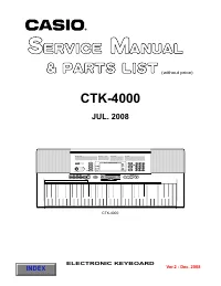
Casio CTK-4000 - User Manual
Casio CTK-4000 – User Manual, read for free online in PDF format. We hope this helps you resolve any issues you may have. If you have further questions, please contact us through the contact form.


Table of Contents:
- Page 2 – CONTENTS
- Page 3 – SPECIFICATIONS
- Page 5 – BLOCK AND WIRING DIAGRAM
- Page 6 – PCB LAYOUT
- Page 7 – NOMENCLATURE OF KEYS; CIRCUIT DESCRIPTION; KEY MATRIX
- Page 8 – BUTTON MATRIX
- Page 9 – PRINTED CIRCUIT BOARDS
- Page 12 – DIAGNOSTIC PROGRAM; Initial Setting; How to start diagnostic program; TESTMODE; Diagnostic program
- Page 15 – EXPLODED VIEW
- Page 16 – PARTS LIST
- Page 19 – SCHEMATIC DIAGRAMS
- Page 26 – Overseas Service Division
"Loading the manual" means you need to wait until the file loads and becomes available for online reading. Some manuals are very large, and the time they take to appear depends on your internet speed.
Was this manual helpful?
About this manual
- Brand
- Casio
- Model
- CTK-4000
- Document type
- User Manual
- Language(s)
- English
- Pages
- 26
- File size
- 4.7 MB
- Format
Other Manuals for Casio CTK-4000
Summary
CONTENTS SPECIFICATIONS ------------------------------------------------------------------------------------------ 1BLOCK AND WIRING DIAGRAM --------------------------------------------------------------------- 3PCB LAYOUT -----------------------------------------------------------------------------...
– 1 – SPECIFICATIONS Keyboard Touch Response Maximum Polyphony Tones Built-in Tones Sampling Tones Functions Reverb Chorus Metronome Beats per Measure Tempo Range Song Bank Built-in Songs User Songs Step Up Lesson Lessons Lesson Part Functions Music Challenge Auto Accompaniment Built-in Rhythms User...
– 3 – BLOCK AND WIRING DIAGRAM KC5~KC7, FI4~ FI7 , SI4~ SI7 KC0~KC4,FI0~FI3,SI0~SI3 MD0 ~ MD15 MD0 ~ MD15 MA1~ MA18 MA1~MA23 VA5 VCP VD5 VA3VDP3VD3 VD3 IC3 IC6 IC2 Power Supply Circuit Q1~Q3,Q7,D105,203 VC VD5 VCP VA5 LVD5 CN22 CN18 CN14 CN15 VD3 CN2 (13pin) CN801 (13pin) CN802 (10pin) CN803 (10pin)...
Ask a question
Related manuals
Popular Casio Other
More Casio Other models
 Casio CTK-2100 User Manual
 Casio CTK-2400 User Manual
 Casio CTK-2500 Manual
 Casio CTK-2550 User Manual
 Casio CTK-3400SK User Manual
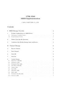 Casio CTK-3500 User Manual
 Casio CTK-5000 User Manual
 Casio CTK-5200 User Manual
 Casio CTK-5300 User Manual
 Casio CTK-6250 User Manual
 Casio CTK-6300in User Manual
 Casio CTK-7000 RU User Manual