Page 2 - NEDERLANDS; Luchtgekoelde waterkoelaggregaten en omkeerbare lucht-water
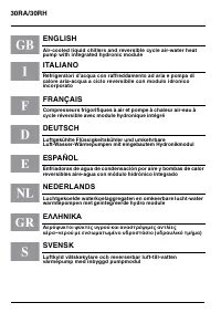
30RA/30RH ENGLISH Air-cooled liquid chillers and reversible cycle air-water heat pump with integrated hydronic module ITALIANO Refrigeratori d’acqua con raffreddamento ad aria e pompa di calore aria-acqua a ciclo reversibile con modulo idronico incorporato FRANçAIS Compresseurs frigorifiques à air e...
Page 3 - ENGLISH; Contents; Page
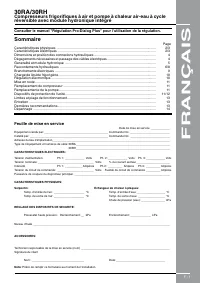
GB - 1 30RA/30RH Air-cooled liquid chillers and reversible air-to-water heat pumps with integrated hydronic module ENGLISH For the use of the control system, refer to the Pro-Dialog Plus control manual. Contents Page Physical data ........................................................................
Page 4 - Physical data and electrical data - Model RA
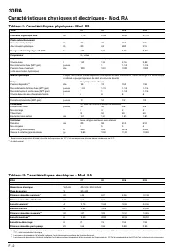
30RA GB - 2 30RA 017 021 026 033 Power supply V-ph-Hz 400-3-50 / 400-3-50+N Voltage range V 360-440 Nominal power input* kW 6.43 8.57 9.56 12.39 Effective power input** kW 6.54 8.72 9.75 12.60 Nominal current drawn* A 10.75 15.50 18.80 24.55 Effective current drawn** A 10.95 15.75 19.10 24.95 Maximu...
Page 5 - Physical data and electrical data - Model RH
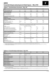
GB - 3 30RH E N G L I S H 30RH 017 021 026 033 Power supply V-ph-Hz 400-3-50 / 400-3-50+N Voltage range V 360-440 Nominal power input* kW 6.21 7.95 9.13 11.83 Effective power input** kW 6.30 8.10 9.30 12.00 Nominal current drawn* A 10.75 14.80 18.70 23.65 Effective current drawn** A 10.90 15.05 19.0...
Page 7 - General information and hydronic module; Unit installation
30RA/30RH GB - 5 E N G L I S H General information and hydronic module Unit installation Read this instruction manual thoroughly before starting the installation.This unit complies with low-voltage (EEC/73/23) and electro- magnetic compatibility (EEC/89/336) directives. • The installation must be ca...
Page 8 - Water connections; Typical water circuit diagram for units with hydronic module
30RA/30RH GB - 6 Water connections Typical water circuit diagram for units with hydronic module Legend for units without hydronic module: 30RA - RH unit without hydronic mo- dule Fan coil units Water circulating pump Expansion vessel Pressure gauges Manual shut-off val- ves Mesh filter...
Page 9 - Ethylene glycol curve
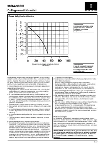
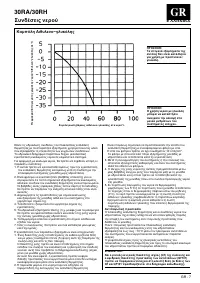
30RA/30RH GB - 7 E N G L I S H Water connections Ethylene glycol curve Freezing temperature of water- ethylene glycol mixture °C Weight concentration of ethylene glycol in water % Make the plate heat exchanger hydraulic connections with the necessary components, using material which will guarantee t...
Page 10 - Water pressure drop of the unit without hydronic module
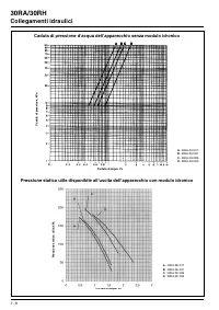
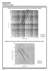
30RA/30RH GB - 8 Water connections Water pressure drop of the unit without hydronic module Outlet available static pressure of the unit with hydronic module Pressure drop , kPa Water flow rate, l/s A. 30RA-RH 017 B. 30RA-RH 021 C. 30RA-RH 026 D. 30RA-RH 033 A vailable static pressure, kPa Water flow...
Page 11 - Electrical connections and refrigerant charge; Electrical connections; Liquid refrigerant charge
30RA/30RH GB - 9 E N G L I S H Electrical connections and refrigerant charge Electrical connections WARNING: To prevent electrical shock or equipment damage, make sure disconnects are open before electrical connections are made. If this action is not taken, personal injury may occur. Power supply ca...
Page 12 - Refrigerant charge and electronic control; Electronic control
30RA/30RH GB - 10 Refrigerant charge and electronic control Undercharge If there is not enough refrigerant in the system, this is indicated by gas bubbles in the moisture sight glass. There are two possibilities:• Small undercharge (bubbles in the sight glass, no significant change in suction pressu...
Page 13 - replacement, unit protection devices; Compressor replacement; Description of unit protection devices
GB - 11 30RA/30RH E N G L I S H Start-up, compressor and pump replacement, unit protection devices Start-up Unit start-up is done by the electronic control described above, and must always be carried out under the supervision of a qualified air conditioning engineer. Necessary checks/precautions bef...
Page 14 - Unit protection devices, operating limits and operating range
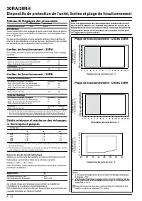
30RA/30RH GB - 12 Unit protection devices, operating limits and operating range Table III: Pressure switch settings Cut-out Reset High pressurestat 30 bar Manual WARNING: Alteration of factory settings other than the design set-point, without manufacturer's authorisation, may void the warranty. In c...
Page 15 - General maintenance, maintenance and final recommendations; General maintenance; Maintenance
GB - 13 30RA/30RH E N G L I S H General maintenance, maintenance and final recommendations General maintenance ATTENTION: Before starting any servicing or maintenance operation on the unit, make sure that the power supply has been disconnected. A current discharge could cause personal injury. In ord...
Page 16 - Troubleshooting
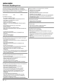
30RA/30RH GB - 14 Troubleshooting A list of possible faults, as well as the probable cause and sugge- sted solutions is shown as follows. In the event of a unit malfunction it is recommended to disconnect the power supply and ascertain the cause. Symptoms Cause remedy Unit does not start : - No powe...
Page 17 - aria-acqua a ciclo reversibile con modulo idronico incorporato; ALIANO; riguarda l’uso del sistema di controllo dell’apparecchio; Indice; Pagina; Controlli all’avviamento
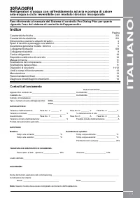
I - 1 30RA/30RH Refrigeratori d’acqua con raffreddamento ad aria e pompa di calore aria-acqua a ciclo reversibile con modulo idronico incorporato IT ALIANO Fare riferimento al manuale del Sistema di controllo Pro-Dialog Plus per quanto riguarda l’uso del sistema di controllo dell’apparecchio Indice ...
Page 18 - Caratteristiche fisiche e caratteristiche elettriche mod. RA
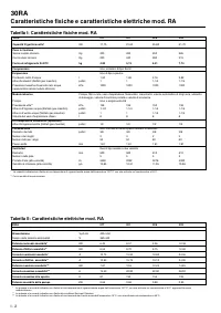
30RA I - 2 30RA 017 021 026 033 Alimentazione V-ph-Hz 400-3-50 Campo delle tensioni ammissibili V 360-440 Potenza nominale assorbita* kW 6,43 8,57 9,56 12,39 Potenza effettiva assorbita** kW 6,54 8,72 9,75 12,60 Corrente nominale assorbita* A 10,75 15,50 18,80 24,55 Corrente effettiva assorbita** A ...
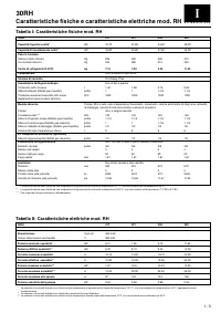
Page 19 - Tabella II: Caratteristiche elettriche mod. RH; Caratteristiche fisiche e caratteristiche elettriche mod. RH
I - 3 30RH I TA L I A N O 30RH 017 021 026 033 Alimentazione V-ph-Hz 400-3-50 Campo delle tensioni ammissibili V 360-440 Potenza nominale assorbita* kW 6,21 7,95 9,13 11,83 Potenza effettiva assorbita** kW 6,30 8,10 9,30 12,00 Corrente nominale assorbita* A 10,75 14,80 18,70 23,65 Corrente effettiva...
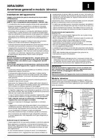
Page 21 - Avvertenze generali e modulo idronico; Installazione dell’apparecchio; Modulo idronico
30RA/30RH I - 5 I TA L I A N O Avvertenze generali e modulo idronico Installazione dell’apparecchio Leggere accuratamente questo manuale prima di procedere all’installazione.L’apparecchio è conforme alle direttive bassa tensione (CEE 73 / 23) e compatibilità elettromagnetica (CEE 89 / 336). • L’inst...
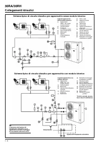
Page 22 - Collegamenti idraulici
30RA/30RH I - 6 Collegamenti idraulici Schema tipico di circuito idraulico per apparecchio con modulo idronico Legenda apparecchio senza modulo idronico: Apparecchio 30RA - RH senza modulo idronico Ventilconvettori Pompa di circolazione acqua Vaso d’espansione Manometri Valvole d’interce...
Page 23 - Curva del glicole etilenico
30RA/30RH I - 7 I TA L I A N O Collegamenti idraulici Curva del glicole etilenico Temperatura di congelamento miscela acqua - glicole etilenico °C Concentrazione in peso del glicole etilenico nell’acqua % I collegamenti idraulici dello scambiatore a piastre devono essere eseguiti usando tutta la com...
Page 25 - Collegamenti elettrici e carica refrigerante; Collegamenti elettrici; Carica del refrigerante in fase liquida
30RA/30RH I - 9 I TA L I A N O Collegamenti elettrici e carica refrigerante Collegamenti elettrici ATTENZIONE: Per prevenire ogni pericolo di folgorazione o di danneggiamento all’apparecchio occorre aprire l’interruttore generale prima di ese- guire i collegamenti elettrici. Il dimensionamento dei c...
Page 26 - Carica refrigerante e dispositivo elettronico di controllo; Dispositivo elettronico di controllo
30RA/30RH I - 10 Carica refrigerante e dispositivo elettronico di controllo NOTA: Eseguire regolarmente delle prove di tenuta ed eliminare immediatamente ogni fuga eventualmente rilevata. Scarsità della carica La scarsità della carica del circuito frigorifero viene denunciata dall’apparizione di bol...
Page 27 - Messa in marcia, sostituzione; Messa in marcia; Sostituzione del compressore; Sostituzione della pompa; Descrizione dei dispositivi di sicurezza
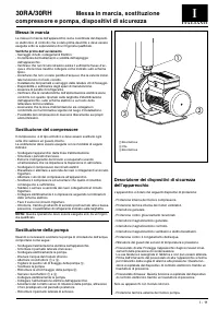
I - 11 30RA/30RH I TA L I A N O Messa in marcia, sostituzione compressore e pompa, dispositivi di sicurezza Messa in marcia La messa in marcia dell’apparecchio viene coordinata dal dispositi- vo elettronico di controllo che è stato prima descritto e deve essere eseguita sotto la supervisione di un f...
Page 28 - Dispositivi di sicurezza, limiti e campi di funzionamento
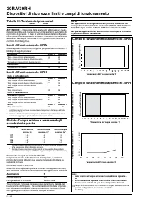
30RA/30RH I - 12 Dispositivi di sicurezza, limiti e campi di funzionamento Tabella III: Tarature dei pressostati Apertura Riarmo Pressostato di alta 30 bar Manuale ATTENZIONE: L’alterazione della taratura di fabbrica senza l’auto- rizzazione scritta della Carrier provoca il decadimento automatico di...
Page 29 - Manutenzione generale, manutenzione; Manutenzione generale; Manutenzione; Raccomandazioni finali
I - 13 30RA/30RH I TA L I A N O Manutenzione generale, manutenzione e raccomandazioni finali Manutenzione generale ATTENZIONE: Prima di intraprendere qualunque operazione di manutenzione sull’apparecchio occorre assicurarsi che sia stata tolta tensione. Le scariche elettriche possono provocare gravi...
Page 30 - Diagnosi e rimedi degli inconvenienti
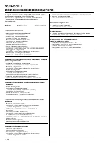
30RA/30RH I - 14 Diagnosi e rimedi degli inconvenienti Di seguito è riportato l’elenco dei possibili inconvenienti, nonché delle possibili cause e dei rimedi per eliminarli. Nel caso in cui l’apparecchio dia problemi, prima di tentare l’accertamento della causa è bene togliere tensione dall’apparecc...
Page 32 - réversible avec module hydronique intégré; FRANÇAIS; Sommaire; Feuille de mise en service
F - 1 30RA/30RH Compresseurs frigorifiques à air et pompe à chaleur air-eau à cycle réversible avec module hydronique intégré FRANÇAIS Consulter le manuel "Régulation Pro-Dialog Plus" pour l'utilisation de la régulation. Sommaire Page Caractéristiques physiques .................................
Page 33 - Caractéristiques physiques et électriques - Mod. RA
30RA F - 2 30RA 017 021 026 033 Alimentation électrique V-ph-Hz 400-3-50 / 400-3-50+N Plage de tension V 360-440 Puissance absorbée nominale* kW 6,43 8,57 9,56 12,39 Puissance absorbée effective** kW 6,54 8,72 9,75 12,60 Intensité nominale* A 10,75 15,50 18,80 24,55 Intensité effective** A 10,95 15,...
Page 34 - Caractéristiques physiques et électriques - Mod. RH
F - 3 30RH FRANçAIS 30RH 017 021 026 033 Alimentation électrique V-ph-Hz 400-3-50 / 400-3-50+N Plage de tension V 360-440 Puissance absorbée nominale* kW 6,21 7,95 9,13 11,83 Puissance absorbée effective** kW 6,30 8,10 9,30 12,00 Intensité nominale* A 10,75 14,80 18,70 23,65 Intensité effective** A ...
Page 36 - Generalité et module hydronique; Installation de l’unité
30RA/30RH F - 5 FRANçAIS Generalité et module hydronique Installation de l’unité Lire attentivement le présent manuel d’installation avant de commencer l’installation.L’unité est conforme aux Directives Basse Tension (CEE/73/23) et Compati bilité Electro-Magnétique (CEE/89/336). • L’installation doi...
Page 37 - Raccordements hydrauliques
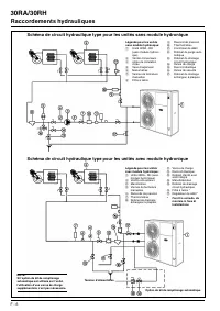
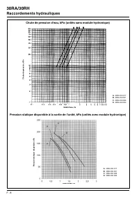
30RA/30RH F - 6 Raccordements hydrauliques Schéma de circuit hydraulique type pour les unités avec module hydronique Légende pour les unités sans module hydronique: Unité 30RA - RH (sans module hydroni- que) Ventilo-convecteurs ompe de circulation d’eau Vase d’expansion Manomètres Vannes...
Page 38 - Courbe d'éthylène glycol
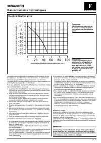
30RA/30RH F - 7 FRANçAIS Raccordements hydrauliques Courbe d'éthylène glycol Température de gel mélange eau-éthylène glycol °C Concentration en poids de l’éthylène glycol dans l’eau % Procéder aux raccordements hydrauliques de l’échangeur de cha- leur à plaques avec les composants nécessaires, en ut...
Page 40 - Branchements électriques et charge de frigorigène; Branchements électriques; Charge de fluide frigorigène
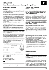
30RA/30RH F - 9 FRANçAIS Branchements électriques et charge de frigorigène Branchements électriques ATTENTION: Pour éviter tout risque d’électrocution ou de dommages matériels, assurez- vous que les disjoncteurs sont ouverts avant d’effectuer les branchements électriques. Ceci pourrait provoquer des...
Page 41 - Charge de liquide frigorigène et régulation électronique; Régulation électronique
30RA/30RH F - 10 Charge de liquide frigorigène et régulation électronique NOTE: Effectuer régulièrement des contrôles de fuite et réparer im- médiatement toute fuite éventuelle . Manque de liquide Le manque de liquide dans le circuit se traduit par l’apparition de bulles de gaz au niveau du voyant l...
Page 42 - Mise en route, remplacement du compresseur; Mise en route; Remplacement du compresseur; Description des dispositifs de protection de
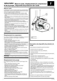
F - 11 30RA/30RH FRANçAIS Mise en route, remplacement du compresseur et de la pompe , dispositifs de protection de l'unité Mise en route Le démarrage de l’unité est réalisé à partir de la commande électro- nique décrite ci- dessus et doit toujours être effectué sous la super- vision d’un ingénieur q...
Page 44 - Entretien général, entretien et dernières recommandations; Entretien général; Entretien
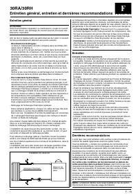
F - 13 30RA/30RH FRANçAIS Entretien général, entretien et dernières recommandations Entretien général ATTENTION: Avant tout entretien/ réparation ou maintenance, couper le courant de l’unité. Sinon, une décharge de courant pourrait provoquer des blessures corporelles. Afin de tirer le meilleur parti...
Page 45 - Dépannage
30RA/30RH F - 14 Dépannage Une liste des pannes éventuelles, ainsi que leur origine probable et les solutions proposées, est présentée ci-après. En cas de dysfonctionnement de l’unité, il est recommandé de couper l’alimentation et de vérifier la cause. Symptômes Cause remède L’unité ne démarre pas :...
Page 46 - DEUTSCH; Inhalt; Seite; Protokoll der inbetriebnahme
D - 1 30RA/30RH Luftgekühlte Flüssigkeitskühler und umkehrbare Luft-Wasser-Wärmepumpen mit eingebautem Hydronikmodul DEUTSCH Für die Verwendung der Regelung auf das Pro-Dialog Plus-Regelungs-Handbuch der Serie 30RA-30RH Bezug nehmen. Inhalt Seite Technische Daten .......................................
Page 47 - Tabelle II: Elektrische Daten - Modell RA; Technische und elektrische Daten - Modell RA
30RA D - 2 30RA 017 021 026 033 Stromversorgung V-Ph-Hz 400-3-50 / 400-3-50+N Spannungsbereich V 360-440 Nennleistungsaufnahme* kW 6,43 8,57 9,56 12,39 Effektive Leistungsaufnahme** kW 6,54 8,72 9,75 12,60 Nennleistungsaufnahme* A 10,75 15,50 18,80 24,55 Effektive Leistungsaufnahme** A 10,95 15,75 1...
Page 48 - Tabelle II: Elektrische Daten - Modell RH; Technische und elektrische Daten - Modell RH
D - 3 30RH D E U T S C H 30RH 017 021 026 033 Stromversorgung V-Ph-Hz 400-3-50 / 400-3-50+N Spannungsbereich V 360-440 Nennleistungsaufnahme* kW 6,21 7,95 9,13 11,83 Effektive Leistungsaufnahme** kW 6,30 8,10 9,30 12,00 Nennleistungsaufnahme* A 10,75 14,80 18,70 23,65 Effektive Leistungsaufnahme** A...
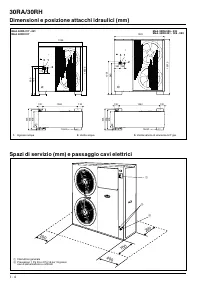
Page 49 - Abmessungen und Positionen der hydraulischen Anschlüsse
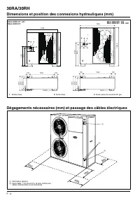
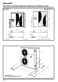
30RA/30RH D - 4 Abmessungen und Positionen der hydraulischen Anschlüsse Erforderlicher freier Raum (mm) und Durchführung der elektrischen Kabel 200 700 200 400 1. Wassereintritt 2. Wasseraustritt 3. Ausgang Gas-Sicherheitsventil 3/4” 1 2 3 1328 1453.5 859 796 175 105 12x20 1068 635 130 130 578 478 4...
Page 50 - Allgemeine Hinweise und Hydronikmodul; Hydronikmodul
30RA/30RH D - 5 D E U T S C H Allgemeine Hinweise und Hydronikmodul Geräte-Installation Dieses Handbuch sorgfältig durchlesen, ehe mit der Installa- tion begonnen wird. Das Gerät entspricht der Niederspannungs-Direktive (EEC 73/23) und der Direktive über elektromagnetische Verträglichkeit (EEC/89/33...
Page 51 - Hydraulikanschlüsse
30RA/30RH D - 6 Hydraulikanschlüsse Typisches Hydraulikkreislauf-Diagramm für Gerät mit Hydronikmodul Legende (Gerät ohne Hydronikmodul): 30RA-RH-Gerät ohne Hydronikmodul Ventilator-Verdam- pfer-Einheiten Wasserumwälzpum- pe Expansionsgefäß Manometer Manuelle Absperr- ventile Siebfilte...
Page 54 - Elektrische Anschlüsse und Kältemittelfüllung; Elektrische Anschlüsse; Einfüllen von flüssigem Kältemittel
30RA/30RH D - 9 D E U T S C H Elektrische Anschlüsse und Kältemittelfüllung Elektrische Anschlüsse ACHTUNG: Um elektrische Schläge oder eine Beschädigung des Geräts zu vermeiden, darauf achten, daß vor dem Herstellen der elektrischen Anschlüsse die Trennschalter geöffnet sind. Wird dies unterlassen,...
Page 55 - Kältemittelfüllung und Elektronikregelung; Elektronikregelung
30RA/30RH D - 10 Kältemittelfüllung und Elektronikregelung ANMERKUNG: Regelmäßige Lecktests durchführen, und eventuell gefundene Lecks sofort beheben. Zu geringe Füllmenge Befindet sich nicht genügend Kältemittel im System, wird dies durch Gasblasen im Feuchtigkeits-Schauglas angezeigt. Es gibt zwei...
Page 56 - Pumpenaustausch und Geräte-Schutzvorrichtungen; Inbetriebnahme; Verdichteraustausch; Pumpenaustausch; Beschreibung der Schutzvorrichtungen
D - 11 30RA/30RH D E U T S C H Inbetriebnahme, Verdichteraustausch, Pumpenaustausch und Geräte-Schutzvorrichtungen Inbetriebnahme Die Geräte-Inbetriebnahme erfolgt immer über die oben beschrie- bene Elektronikregelung und muß unter Aufsicht eines qualifizierten Kältetechnikers erfolgen. Erste Überpr...
Page 57 - Betriebsgrenzen - 30RA; Plattenwärmetauscher
30RA/30RH D - 12 Geräte-Schutzvorrichtungen, Betriebsgrenzen und Betriebsbereich Tabelle III: Druckschalter-Einstellungen Ein Rückstellung Hochdruckschalter 30 bar Manuell WARNUNG: Eine Veränderung der werkseitigen Einstellungen außer dem Auslegungs-Sollwert ohne vorherige Genehmigung des Hersteller...
Page 58 - Allgemeine Instandhaltung, Wartung; Allgemeine Instandhaltung; Wartung; Abschliessende Empfehlungen
D - 13 30RA/30RH D E U T S C H Allgemeine Instandhaltung, Wartung und abschliessende Empfehlungen Allgemeine Instandhaltung ACHTUNG: Ehe irgendwelche Wartungs- und Instandhaltungs-Arbeiten am Gerät vorgenommen werden, sicherstellen, daß die Stromversor- gung abgetrennt worden ist. Ein Stromschlag ka...
Page 59 - Störungsermittlung
30RA/30RH D - 14 Störungsermittlung Nachstehend eine Liste der möglichen Fehler, ebenso wie ihrer möglichen Ursachen und empfohlenen Lösungen. Bei einer Gerätestörung wird empfohlen, die Stromversorgung abzuschalten und die Ursache zu ermitteln. Symptom Ursache abhilfe Gerät läuft nicht an: - Keine ...
Page 60 - ESP; Índice; Página; Lista de verificacion de puesta en marcha
E - 1 30RA/30RH Enfriadoras de agua de condensación por aire y bombas de calor re- versibles aire-agua con módulo hidrónico integrado ESP AÑOL Para utilizar el Control, consultar el manual de instrucciones del Control Pro-Dialog Plus. Índice Página Datos físicos.........................................
Page 61 - Datos físicos y datos eléctricos - Modelo RA
30RA E - 2 30RA 017 021 026 033 tensión nominal V-ph-Hz 400-3-50 / 400-3-50+N Rango tensión V 360-440 Consumo nominal* kW 6,43 8,57 9,56 12,39 Consumo efectivo** kW 6,54 8,72 9,75 12,60 Corriente nominal* A 10,75 15,50 18,80 24,55 Corriente efectiva** A 10,95 15,75 19,10 24,95 Corriente máxima*** kW...
Page 62 - Datos físicos y datos eléctricos - Modelo RH
E - 3 30RH E S P A Ñ O L 30RH 017 021 026 033 tensión nominal V-ph-Hz 400-3-50 / 400-3-50+N Rango tensión V 360-440 Consumo nominal* kW 6,21 7,95 9,13 11,83 Consumo efectivo** kW 6,30 8,10 9,30 12,00 Corriente nominal* A 10,75 14,80 18,70 23,65 Corriente efectiva** A 10,90 15,05 19,05 24,00 Corrient...
Page 64 - información general y módulo hidrónico; Para la instalación
30RA/30RH E - 5 E S P A Ñ O L información general y módulo hidrónico Para la instalación Leer este manual cuidadosamente antes de comenzar la instalación.La máquina es conforme a las Directivas Baja tensión (CEE/73/23) y Compatibi lidad Electromagnético (CEE/89/336). • La instalación debería realiza...
Page 65 - Conexiones hidráulicas
30RA/30RH E - 6 Conexiones hidráulicas Esquema típico del circuito de agua de las unidades con módulo hidrónico Leyenda de las unidades sin módulo hidrónico: Unidad 30RA - RH sin módulo hidrónico Unidades fan-coil Bomba aceleradora de agua Vaso de expansión Manómetros Válvulas de cierre ...
Page 66 - Curva de etilenglicol
30RA/30RH E - 7 E S P A Ñ O L Conexiones hidráulicas Curva de etilenglicol temperatura de congelación mezcla agua - glicol etilénico °C Concentración en peso del glicol etilénico en agua % Efectuar Ias conexiones de agua del intercambiador mediante los elementos necesarios, utilizando en Ias uniones...
Page 67 - Caída de presión en el agua de la unidad sin módulo hidrónico
30RA/30RH E - 8 Conexiones hidráulicas Caída de presión en el agua de la unidad sin módulo hidrónico Presión estática disponible a la salida de la unidad con módulo hidrónico Caída de presión, kPa Caudal de agua, l/s A. 30RA-RH 017 B. 30RA-RH 021 C. 30RA-RH 026 D. 30RA-RH 033 Presión estática dispon...
Page 68 - Conexiones eléctricas y carga de refrigerante; Conexiones eléctricas; Carga de refrigerante líquido
30RA/30RH E - 9 E S P A Ñ O L Conexiones eléctricas y carga de refrigerante Conexiones eléctricas PRECAUCiÓn: Pare prevenir descargas eléctricas o daños en el equipo, ase- gurarse de que los seccionadores de alimentación están abier- tos antes de efectuar ias conexiones eléctricas. De no hacerse así...
Page 69 - Carga de refrigerante y control electrónico; Control electrónico
30RA/30RH E - 10 Carga de refrigerante y control electrónico Carga insuficiente Si no hay suficiente refrigerante en el sistema, se verán burbujas de gas en el visor de humedad. Existen dos posibilidades: • Carga ligeramente insuficiente (burbujas en el visor, ningún cam - bio significativo en la pr...
Page 70 - presor y de la bomba, dispositivos de protección de la unidad; Puesta en marcha; Sustitución del compresor; Descripción de los dispositivos de protec-
E - 11 30RA/30RH E S P A Ñ O L Puesta en marcha, sustitución del com- presor y de la bomba, dispositivos de protección de la unidad Puesta en marcha La puesta en servicio de la unidad se realiza mediante los mandos electrónicos descritos anteriormente, y siempre bajo la supervisión de un técnico cua...
Page 72 - Mantenimiento general, mantenimiento y; Mantenimiento general; Mantenimiento
E - 13 30RA/30RH E S P A Ñ O L Mantenimiento general, mantenimiento y recomendaciones finales Mantenimiento general AtEnCiÓn: Antes de iniciar cualquier operación de servicio o mantenimlento de la unidad, asegurarse de que se ha desconectado la alimentación eléctrica. Una descarga puede causar daños...
Page 73 - Localización de averías
30RA/30RH E - 14 Localización de averías A continuación figura una lista de posibles averías junto con la cau - sa probable y las soluciones sugeridas. En caso de mal funciona- miento de una unidad, se recomienda desconectar la alimentación eléctrica y averiguar la causa. Síntomas Causa remedio La u...
Page 74 - mtepompen met geïntegreerde hydro module; Inhoud; Checklist voor de inbedrijfstelling
NL - 1 30RA/30RH Luchtgekoelde waterkoelaggregaten en omkeerbare lucht-water war- mtepompen met geïntegreerde hydro module NEDERLANDS Zie voor bediening van de regeling het boekje 30RA/RH/RY/RYH serie Pro-Dialog Plus regeling. Inhoud BLZ. Technische gegevens ............................................
Page 75 - Technische- en elektrische gegevens - type RA
30RA NL - 2 30RA 017 021 026 033 Elektrische voeding V-f-Hz 400-3-50 / 400-3-50+N Netspanningslimieten V 360-440 Nominaal opgenomen vermogen* kW 6,43 8,57 9,56 12,39 Effectief opgenomen vermogen** kW 6,54 8,72 9,75 12,60 Nominaal opgenomen stroom* A 10,75 15,50 18,80 24,55 Effectief opgenomen stroom...
Page 76 - Technische- en elektrische gegevens - type RH
NL - 3 30RH NEDERLANDS 30RH 017 021 026 033 Elektrische voeding V-f-Hz 400-3-50 / 400-3-50+N Netspanningslimieten V 360-440 Nominaal opgenomen vermogen* kW 6,21 7,95 9,13 11,83 Effectief opgenomen vermogen** kW 6,30 8,10 9,30 12,00 Nominaal opgenomen stroom* A 10,75 14,80 18,70 23,65 Effectief opgen...
Page 78 - Algemene informatie en hydro module; Montage van de unit; Hydro module
30RA/30RH NL - 5 NEDERLANDS Algemene informatie en hydro module Montage van de unit Lees deze handleiding zorgvuldig voordat u met de montage begint.Dit apparaat voldoet aan de laagspannings-richtlijn 73/23EEG (veiligheid) en aan EMC richtlijn 89/336EEG voor elektroma- gnetische compatibiliteit. • M...
Page 79 - Wateraansluitingen; Voorbeeld van een watercircuit voor unit met hydro module; Voorbeeld van een watercircuit voor unit zonder hydro module
30RA/30RH NL - 6 Wateraansluitingen Voorbeeld van een watercircuit voor unit met hydro module Verklaring (unit zonder hydro module): 30RA-RH unit zonder hydro module Ventilatorconvectoren Waterpomp Expansievat Manometers Handbediende afslui- ters Filter Drukmeetpunt Thermometers ...
Page 80 - Ethyleen-glycol curve
30RA/30RH NL - 7 NEDERLANDS Wateraansluitingen Ethyleen-glycol curve V riespunt mengsel water – ethyleenglycol °C Concentratie in gewicht van de ethyleenglycol in het water % Maak de waterzijdige aansluitingen van de platenwarmtewisselaar. Gebruik hiervoor gereedschap waarmee de aansluitingen absolu...
Page 82 - Elektrische aansluiting en koelmiddelvulling; Elektrische aansluiting; Koudemiddelvulling
30RA/30RH NL - 9 NEDERLANDS Elektrische aansluiting en koelmiddelvulling Elektrische aansluiting WAARSCHUWING: Schakel ALTIJD de hoofdstroom af voordat met werkzaamheden aan de unit wordt begonnen! Het niet opvolgen van deze regels kan leiden tot persoonlijk letsel.De afmetingen van de voedingskabel...
Page 83 - Koelmiddelvulling en ektronische regeling; Elektronische regeling
30RA/30RH NL - 10 Koelmiddelvulling en ektronische regeling OPMERKING: Voer regelmatig een lektest uit en repareer een lek onmiddellijk. Te weinig koudemiddel Als er belletjes in het kijkglas zichtbaar zijn, dan betekent dit dat er onvoldoende koudemiddel in het systeem aanwezig is. Er zijn twee mog...
Page 84 - Inbedrijfstelling, vervangen compressor; Inbedrijfstelling; Vervangen van de compressor; Vervangen van de pomp
NL - 11 30RA/30RH NEDERLANDS Inbedrijfstelling, vervangen compressor en pomp, machinebeveiligingen Inbedrijfstelling Inbedrijfstelling vindt plaats d.m.v. de hierboven beschreven elektro- nische regeling en mag alleen worden uitgevoerd door deskundig personeel. Controle/voorzorgsmaatregelen voor de ...
Page 85 - Beveiligingen, bedrijfslimieten en bedrijfsbereik
30RA/30RH NL - 12 Beveiligingen, bedrijfslimieten en bedrijfsbereik Tabel III: Instellingen drukschakelaar Schakelt uit bij Reset Hogedrukbeveiliging 30 bar Handmatig WAARSCHUWING: Wanneer de fabriekinstellingen (uitgezonderd het ontwerp-setpoint) zonder toestemming van Carrier worden gewijzigd, ver...
Page 86 - Onderhoud - algemeen, specifiek en aanbevelingen; Onderhoud - Specifiek; Aanbevelingen
NL - 13 30RA/30RH NEDERLANDS Onderhoud - algemeen, specifiek en aanbevelingen Onderhoud - Algemeen WAARSCHUWING: Schakel de hoofdstroom af voordat met werkzaam he den aan de unit wordt begonnen. Het niet opvolgen van deze waarschuwing kan leiden tot zwaar lichamelijk letsel.Voor een goede werking mo...
Page 87 - Storingzoeken
30RA/30RH NL - 14 Storingzoeken Hieronder is een lijst opgenomen met mogelijke storingen en hun oplossingen. Als er een storing optreedt, schakel dan de hoofdstroom af en stel de oorzaak vast. Klacht Oorzaak oplossing Unit start niet: - Voeding onderbroken; aanschakelen . - Hoofdschakelaar uit; aans...
Page 88 - Pro-Dialog Plus.
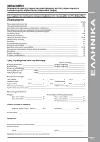
GR - 1 30RA/30RH − ( ) K Pro-Dialog Plus. ....................................
Page 89 - RA; RA
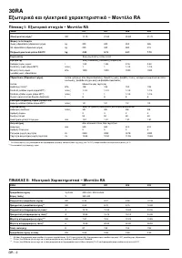
30RA GR - 2 30RA 017 021 026 033 * kW 17.70 21.60 25.80 31.70 ( ) kg 200 220 250 285 ( ) kg 220 240 280 315 R-407C kg 4.80 5.13 6.41 7.70 scroll ...
Page 90 - RH
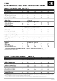
GR - 3 30RH E HNIKA 30RH 017 021 026 033 V-ph-Hz 400-3-50 / 400-3-50+N V 360-440 * kW 6.21 7.95 9.13 11.83 ** kW 6.30 8.10 9.30 12.00 * A 10.75 14.80 18.70 23.65 ...
Page 93 - K K ; K K
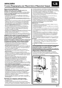
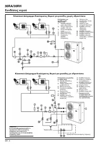
30RA/30RH GR - 6 K K 30 RA-RH ( fan coil) ...
Page 102 - inbyggd pumpmodul; SVENSKA; Innehåll; Sida; Igångkörning - kontrollista
S - 1 30RA/30RH Luftkyld vätskekylare och reverserbar luft-till-vatten värmepump med inbyggd pumpmodul SVENSKA För instruktioner om styrning hänvisas till Pro-Dialog Plus styrmanual. Innehåll Sida Tekniska data ............................................................................................
Page 103 - Tekniska och elektriska data - modell RA
30RA S - 2 30RA 017 021 026 033 Kraftmatning V-fas-Hz 400-3-50 / 400-3-50+N Spänningsområde V 360-440 Nominell tillförd eleffekt* kW 6,43 8,57 9,56 12,39 Effektiv tillförd eleffekt** kW 6,54 8,72 9,75 12,60 Nominell strömförbrukning* A 10,75 15,50 18,80 24,55 Effektiv strömförbrukning** A 10,95 15,7...
Page 104 - Tekniska och elektriska data - modell RH
S - 3 30RH S V E N S K A 30RH 017 021 026 033 Kraftmatning V-fas-Hz 400-3-50 / 400-3-50+N Spänningsområde V 360-440 Nominell tillförd eleffekt* kW 6,21 7,95 9,13 11,83 Effektiv tillförd eleffekt** kW 6,30 8,10 9,30 12,00 Nominell strömförbrukning* A 10,75 14,80 18,70 23,65 Effektiv strömförbrukning*...
Page 106 - Allmän information och pumpmodul; Enhetens installation
30RA/30RH S - 5 S V E N S K A Allmän information och pumpmodul Enhetens installation Läs noga igenom denna drift- och skötselinstruktion innan installation påbörjas.Enheten följer de direktiv som rekommenderas i EEC/73/23 och EEC/89/336. • Installationen skall utföras av en kvalificerad kyltekniker....
Page 107 - Vattenanslutningar; Schematiskt rördiagram för enheter med pumpmodul; Schematiskt rördiagram för enheter utan pumpmodul
30RA/30RH S - 6 Vattenanslutningar Schematiskt rördiagram för enheter med pumpmodul Förklaring (enheter utan pumpmodul): 30RA - RH utan pumpmodul Fläktkonvektorer Cirkulationspump Expansionskärl Tryckmanometrar Manuella avstän- gningsventiler Nätfilter Tryckuttag Termometrar Flöd...
Page 109 - Vattentryckfall, enhet utan pumpmodul
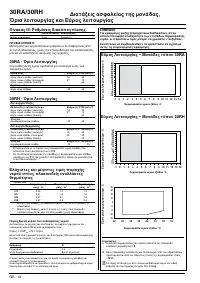
30RA/30RH S - 8 Vattenanslutningar Vattentryckfall, enhet utan pumpmodul Tillgängligt statiskt tryck, enhetens utgång (enheter med pumpmodul), kPa Tryckfall, kPa Flöde l/s A. 30RA-RH 017 B. 30RA-RH 021 C. 30RA-RH 026 D. 30RA-RH 033 Statiskt tryckkapacitet, kPa Flöde l/s A. 30RA-RH 017 B. 30RA-RH 021...
Page 110 - Elektriska anslutningar och köldmediefyllning; Elektriska anslutningar; Köldmediefyllning i vätskefas
30RA/30RH S - 9 S V E N S K A Elektriska anslutningar och köldmediefyllning Elektriska anslutningar VARNING: För att förhindra elektriska stötar eller skada på utrustningen; se till att nätspänningen är frånslagen innan elektriska anslutningar genomförs. Dimensioneringen av matarkablarna och respekt...
Page 111 - Köldmediefyllning och elektronisk styrning; Elektronisk styrning
30RA/30RH S - 10 Köldmediefyllning och elektronisk styrning Underfyllning Om det inte finns tillräckligt med köldmedium i systemet indikeras detta av gasbubblor i synglaset. Det finns två möjligheter:• Liten underfyllning (bubblor i synglaset, ingen större förändring av förångningstrycket) - Efter u...
Page 112 - Igångsättning, ersättning av pump och; Igångsättning; Ersättning av kompressor; Ersättning av pump; Beskrivning av enhetens skyddsutrustning
S - 11 30RA/30RH S V E N S K A Igångsättning, ersättning av pump och kompressor, skyddsutrustning Igångsättning Enhetens igångsättning utförs av den tidigare beskrivna elektronis- ka styrningen. Igångsättning måste alltid ske under överinseende av en kvalificerad kyltekniker. Nödvändiga kontroller i...
Page 113 - Enhetens skyddsutrustning, driftsgränser och driftsområde
30RA/30RH S - 12 Enhetens skyddsutrustning, driftsgränser och driftsområde Tabell III: Pressostatinställningar Frånslag Återställning Högtryckspressostat 30 bar Manuell VARNING: Ändring av fabriksutförda inställningar, förutom börvärdet, utan tillverkarens godkännande kan leda till att garantin förk...
Page 114 - Underhåll och slutliga rekommendationer; Allmän information; Underhåll
S - 13 30RA/30RH S V E N S K A Underhåll och slutliga rekommendationer Allmän information VIKTIGT: Innan enheten startas eller serviceåtgärder utförs, se till att kraft- matningen slagits ifrån. Ansluten ström kan leda till personskada. För att uppnå maximal prestanda skall särskild hänsyn tas till ...
Page 115 - Felsökning
30RA/30RH S - 14 Felsökning Här följer en lista med möjliga fel och tänkbara orsaker samt förslag på åtgärder. Om något fel uppstår, slå ifrån enhetens kraftmatning och försök finna orsaken. Symptom Orsak ÅTGÄRD Enheten startar inte: - Ingen kraftmatning; ANSLUT KRAFTMATNING . - Öppen huvudbrytare; ...