Page 2 - Your safety and the safety of others are very important.; DANGER
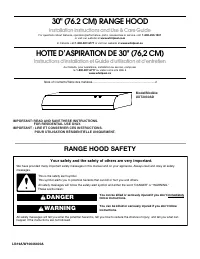
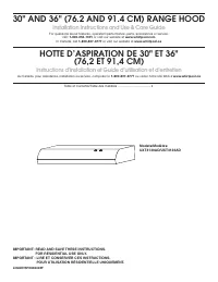
2 TABLE OF CONTENTS TABLE DES MATIÈRES RANGE HOOD SAFETY You can be killed or seriously injured if you don't immediately You can be killed or seriously injured if you don't follow All safety messages will tell you what the potential hazard is, tell you how to reduce the chance of injury, and tell yo...
Page 3 - IMPORTANT SAFETY INSTRUCTIONS; READ AND SAVE THESE INSTRUCTIONS
3 IMPORTANT SAFETY INSTRUCTIONS READ AND SAVE THESE INSTRUCTIONS
Page 4 - INSTALLATION REQUIREMENTS; Tools and Parts; Location Requirements
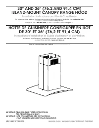
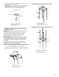
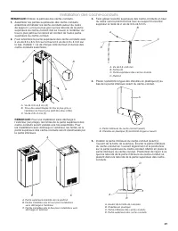
4 INSTALLATION REQUIREMENTS Tools and Parts Gather the required tools and parts before starting installation. Read and follow the instructions provided with any tools listed here. Tools Needed ■ Level ■ Drill with 1 1 / 4 " (3.2 cm), 3 / 8 " (9.5 mm), 1 / 8 " (3.2 mm) and 7 / 64 " (...
Page 5 - Venting Requirements
5 Product Dimensions A. 12 1 / 8 "(30.8 cm) B. 13 3 / 16 "(33.5 cm) C. *28 5 / 8 "(72.7 cm) min. 493/ 8 "(125.4 cm) max. **281/ 16 "(71.3 cm) min. 441/ 2 "(113.1 cm) max. D. 25 11 / 16 "(65.3 cm) E. 30"(76 cm) or 36"(91.2 cm) A B C D E * For non-vented (recirculat...
Page 6 - Electrical Requirements
6 Makeup Air Local building codes may require the use of makeup air systems when using ventilation systems greater than specified CFM of air movement. The specified CFM varies from locale to locale. Consult your HVAC professional for specific requirements in your area. Venting Methods This island ho...
Page 7 - INSTALLATION INSTRUCTIONS; Prepare Location; WARNING
7 INSTALLATION INSTRUCTIONS Prepare Location ■ Lay out the vent duct system before installing the range hood to determine the best routing for the vent duct. ■ It is recommended that the vent system be installed before hood is installed. ■ Before making cutouts, make sure there is proper clearance w...
Page 8 - Assemble Range Hood
8 Install In-Line Smart Kit - Optional NOTE: Your range hood can work with either an internal or an inline (external) blower motor system. An optional In-Line Smart Kit (purchased separately) allows the blower motor that comes with this range hood to be installed in a location other than inside the ...
Page 9 - Install Range Hood
9 5. Using 2 or more people, lift the range hood assembly under the structure. A B A. Lower vertical supportsB. Range hood assembly 6. Attach the range hood assembly to the lower vertical supports with 2 leveling screws and 2 nuts. A B C D A. 2 - Leveling screwsB. Lower vertical support C. Place lev...
Page 10 - Make Electrical Connection
10 Make Electrical Connection 1. Disconnect power. 2. Remove terminal box cover. 3. Remove the knockout in the terminal box and install a UL listed or CSA approved 1 / 2 " strain relief. A C B A. Terminal boxB. KnockoutC. Terminal box cover 4. Run home power supply cable through strain relief in...
Page 11 - Install Duct Covers
11 Install Duct Covers NOTE: Remove protective film from the duct covers. 1. Assemble the upper duct covers together and install the duct covers around the support frame. The larger hole in the flanges of the upper duct cover must be outside the smaller hole in the mating flange of the other upper d...
Page 12 - Complete Installation
12 6. Install the lower duct cover (rear) to the range hood canopy. Spread the lower duct cover opening slightly and position it over the upper duct cover. Set the lower duct cover in place. Position so the flanges of the lower duct cover set into the flanges of the upper duct cover. Make sure the f...
Page 13 - RANGE HOOD USE; Range Hood Controls
13 RANGE HOOD USE The range hood is designed to remove smoke, cooking vapors, and odors from the cooktop area. For best results, start the hood before cooking, and allow it to operate several minutes after the cooking is complete to clear all smoke and odors from the kitchen.The hood controls are lo...
Page 14 - RANGE HOOD CARE; Cleaning
14 RANGE HOOD CARE Cleaning IMPORTANT: Clean the hood and grease filters frequently according to the following instructions. Replace grease filters before operating hood. Exterior Surfaces To avoid damage to the exterior surface, do not use steel wool or soap-filled scouring pads.Always wipe dry to ...
Page 15 - WIRING DIAGRAM; LED
15 WIRING DIAGRAM L REMOTE SWITCH FOR ADA COMPLIANCE ADD THESE ELEMENTS DURING THE INSTALLATION. SEL0169984 Mechanical Push Buttons (4 button 3 Speeds) LED LED M BR YL YL 3 2 1 4 5 6 7 8 9 RD BR WH BU GY BK WH BU BK 12.5uF WH BK BK YL - GN BK BU WH BR YL BR WH WH YL WH PUSH BUTTON SWITCH OPERATION F...
Page 16 - ASSISTANCE OR SERVICE; In Canada
16 ASSISTANCE OR SERVICE If You Need Service Please refer to the warranty page in this manual. If You Need Replacement Parts If you need to order replacement parts, we recommend that you use only factory specified parts. Factory specified parts will fit right and work right because they are made wit...
Page 17 - SÉCURITÉ DE LA HOTTE DE CUISINIÈRE; Votre sécurité et celle des autres est très importante.; AVERTISSEMENT
17 SÉCURITÉ DE LA HOTTE DE CUISINIÈRE Risque possible de décès ou de blessure grave si vous ne suivez pas immédiatement les instructions. Risque possible de décès ou de blessure grave si vous ne suivez pas les instructions. Tous les messages de sécurité vous diront quel est le danger potentiel et vo...
Page 18 - IMPORTANTES INSTRUCTIONS DE SÉCURITÉ; LIRE ET CONSERVER CES INSTRUCTIONS
18 IMPORTANTES INSTRUCTIONS DE SÉCURITÉ LIRE ET CONSERVER CES INSTRUCTIONS AVERTISSEMENT : POUR RÉDUIRE LE RISQUE D'INCENDIE, CHOC ÉLECTRIQUE OU DOMMAGES CORPORELS, RESPECTER LES INSTRUCTIONS SUIVANTES : ■ Utiliser cet appareil uniquement dans les applications envisagées par le fabricant. Pour toute...
Page 19 - EXIGENCES D’INSTALLATION; Outils et pièces; Exigences d’emplacement
19 EXIGENCES D’INSTALLATION Outils et pièces Rassembler les outils et pièces nécessaires avant d’entreprendre l’installation. Lire et observer les instructions fournies avec chacun des outils de la liste ci-dessous. Outils nécessaires ■ Niveau ■ Perceuse avec forets de 11/ 4 " (3,2 cm), 3/ 8 ...
Page 20 - Exigences concernant l’évacuation
20 Dimensions du produit A. 12 1 / 8 "(30.8 cm) B. 13 3 / 16 "(33.5 cm) C. *28 5 / 8 "(72.7 cm) min. 493/ 8 "(125.4 cm) max. **281/ 16 "(71.3 cm) min. 441/ 2 "(113.1 cm) max. A B C D E D. 25 11 / 16 "(65.3 cm) E. 30"(76 cm) or 36"(91.2 cm) *Pour installations sans...
Page 21 - Spécifications électriques
21 Méthodes d’évacuation Cette hotte a été configurée à l'usine pour la décharge de l'air aspiré à travers le toit ou à travers un mur.Un circuit d'évacuation en conduit rond de 6" (15,2 cm) (non fourni) est nécessaire pour l'installation. La hotte comporte une ouverture de sortie de diamètre 6&...
Page 22 - INSTRUCTIONS D’INSTALLATION; Préparation de l’emplacement
22 INSTRUCTIONS D’INSTALLATION Préparation de l’emplacement ■ Installer le système d’évacuation avant la hotte pour déterminer le meilleur passage pour le circuit d’évacuation. ■ Il est recommandé que l’installation du circuit d’évacuation soit réalisée avant celle de la hotte. ■ Avant d’exécuter le...
Page 23 - Assemblage de la hotte
23 4. Fixer le support horizontal supérieur à l’aide de 4 vis à bois à tête cruciforme no 2 de 5 x 45 mm. IMPORTANT: Les vis du support horizontal supérieur doivent être vissées dans une structure de soutien du plafond capable de soutenir une charge de 80 lb (36,6 kg). A B A. Support horizontal supé...
Page 25 - Installation de la hotte; Raccordement électrique
25 Installation de la hotte Installation sans décharge à l’extérieur (recyclage) 1. Fixer le déflecteur d’air au support horizontal supérieur à l’aide des 4 vis de montage. B B A A. DéflecteurB. Vis de montage 2. Mesurer la longueur nécessaire de conduit d’évacuation de 6" (15,2 cm) pour le racc...
Page 27 - Installation des cache-conduits
27 Installation des cache-conduits REMARQUE: Enlever la pellicule des cache-conduits. 1. Assembler les parties supérieures des cache-conduits ensemble et installer les cache-conduits autour du cadre de support. Le trou le plus gros sur les rebords de la partie supérieure du cache-conduit doit se tro...
Page 28 - Achever l’installation
28 6. Installer la partie inférieure du cache-conduit (arrière) à l’auvent de la hotte de cuisinière. Écarter la partie inférieure du cache-conduit en l’ouvrant légèrement et la positionner sur la partie supérieure du cache-conduit. Mettre en place la partie inférieure du cache-conduit. Positionner ...
Page 29 - UTILISATION DE LA HOTTE; Commandes de la hotte de cuisinière
29 UTILISATION DE LA HOTTE La hotte de cuisinière est conçue pour extraire fumée, vapeurs de cuisson et odeurs de la zone de la table de cuisson. Pour obtenir les meilleurs résultats, mettre le ventilateur de la hotte en marche avant d’entreprendre une cuisson, et laisser le ventilateur fonctionner ...
Page 30 - ENTRETIEN DE LA HOTTE; Nettoyage
30 ENTRETIEN DE LA HOTTE Nettoyage IMPORTANT : Nettoyer fréquemment la hotte et les filtres à graisse en suivant les instructions suivantes. Réinstaller les filtres à graisse avant de faire fonctionner la hotte. Surfaces externes Afin d'éviter d'endommager la surface externe, ne pas utiliser de tamp...
Page 31 - SCHÉMA DE CÂBLAGE; DEL
31 SCHÉMA DE CÂBLAGE Ph COMMUTATEUR À DISTANCE POUR LA CONFORMITÉ ADA,AJOUTEZ CES ÉLÉMENTS LORS DE L'INSTALLATION. Commutateur du bouton-poussoir (4 boutons 3 Vitesses) SEL0169984 DEL DEL Neu Terre M MAR JA JA 3 2 1 4 5 6 7 8 9 R MAR BL BU GRIS N BL BU N 12.5uF BL N N JA-VE N BU BL MAR JA MAR BL BL ...
Page 32 - ASSISTANCE OU SERVICE; Au Canada
ASSISTANCE OU SERVICE Si vous avez besoin de service Consulter la page de garantie du présent manuel. Si vous avez besoin de pièces de rechange Si vous avez besoin de commander des pièces de rechange, nous vous recommandons d'utiliser seulement des pièces spécifiées par l'usine. Les pièces spécifiée...