Summit Appliance CR2110WHE - Manuals
User Manual Summit Appliance CR2110WHE


Summary
1 Table of Contents Product Specifications ...................................................................................... 2 Installation Instructions for Ceramic Glass Cooktops ............................. 3 - 10 Step #1: Unpacking the Cooktop ..................................................
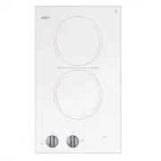
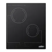
2 Product Specifications Single Burner CR1115: 120V AC – one 6” (140 mm) burner @ 1200 watts Overall dimensions: 11 ⅞ ”W x 12 ⅝ ”D x 3 ⅜ ”H (302 mm x 321 mm x 85,7 mm) Cutout dimensions: 11 ⅛ ”W x 11 ⅞ ”D (282 mm x 302 mm) Double Burner CR2110: 120V AC – two 6” (140 mm) burners @ 1200 watts each CR2...
3 Contour Cooktop Installation Instructions for Ceramic Glass Cooktops Step #1 Unpacking the Cooktop Carefully unpack the cooktop from its shipping container. If possible, retain the original shipping carton and protective packaging in the event the unit ever has to be returned for service. Verify a...
Summit Appliance Hobs Manuals
-
 Summit Appliance CCE211WH
User Manual
Summit Appliance CCE211WH
User Manual
-
 Summit Appliance CCE212BL
User Manual
Summit Appliance CCE212BL
User Manual
-
 Summit Appliance CCE213SS
User Manual
Summit Appliance CCE213SS
User Manual
-
 Summit Appliance CCE227SS
User Manual
Summit Appliance CCE227SS
User Manual
-
 Summit Appliance CR2110B
User Manual
Summit Appliance CR2110B
User Manual
-
 Summit Appliance CR2220B
User Manual
Summit Appliance CR2220B
User Manual
-
 Summit Appliance CR2B120
User Manual
Summit Appliance CR2B120
User Manual
-
 Summit Appliance CR2B120B
User Manual
Summit Appliance CR2B120B
User Manual
-
 Summit Appliance CR2B121
User Manual
Summit Appliance CR2B121
User Manual
-
 Summit Appliance CR2B121B
User Manual
Summit Appliance CR2B121B
User Manual
-
 Summit Appliance CR2B122S
User Manual
Summit Appliance CR2B122S
User Manual
-
 Summit Appliance CR2B12ST
User Manual
Summit Appliance CR2B12ST
User Manual
-
 Summit Appliance CR2B12STE
User Manual
Summit Appliance CR2B12STE
User Manual
-
 Summit Appliance CR2B15T1B
User Manual
Summit Appliance CR2B15T1B
User Manual
-
 Summit Appliance CR2B15T2W
User Manual
Summit Appliance CR2B15T2W
User Manual
-
 Summit Appliance CR2B223G
User Manual
Summit Appliance CR2B223G
User Manual
-
 Summit Appliance CR2B223GL
User Manual
Summit Appliance CR2B223GL
User Manual
-
 Summit Appliance CR2B224S
User Manual
Summit Appliance CR2B224S
User Manual
-
 Summit Appliance CR2B224SS
User Manual
Summit Appliance CR2B224SS
User Manual
-
 Summit Appliance CR2B228T
User Manual
Summit Appliance CR2B228T
User Manual