Page 2 - TABLE OF CONTENTS; IMPORTANT SAFETY INSTRUCTIONS; SAFETY LOGOS
2 3 TABLE OF CONTENTS IMPORTANT SAFETY INSTRUCTIONS ................................... 2GENERAL POWER TOOL SAFETY WARNINGS .................... 3SAFETY INSTRUCTIONS FOR MITERE SAW......................... 4PROPOSITION 65 WARNING ................................................... 5POWER CONNECTIONS...
Page 3 - GENERAL POWER TOOL SAFETY WARNINGS
3 GENERAL POWER TOOL SAFETY WARNINGS The term “power tool” in the warnings refers to your mains-operated (corded) power tool or BATTERY-operated (cordless) power tool. 1) Work area safety a) Keep work area clean and well lit. Cluttered or dark areas invite accidents. b) Do not operate power tools in...
Page 5 - POWER CONNECTIONS; SAVE THESE INSTRUCTIONS.; PROPOSITION 65 WARNING:
5 POWER CONNECTIONS SAVE THESE INSTRUCTIONS. Refer to them often and use them to instruct others. If tool is loaned to someone, also loan them these instructions. A separate electrical circuit should be used for your machines. This circuit should not be less than #12 wire and should be protected wit...
Page 6 - ELECTRICAL CONNECTION
6 7 POWER CONNECTIONS FEATURES This tool has a precision-built electric motor. It should be connected to a POWER SUPPLY THAT IS 120 VOLTS, 60 HZ, AC ONLY (NORMAL HOUSEHOLD CURRENT). Do not operate this tool on direct current (DC). A substantial voltage drop will cause a loss of power and the motor w...
Page 7 - FEATURES; KNOW YOUR COMPOUND MITRE SAW
7 FEATURES Refer to Figure 1. Using this tool safely requires that you understand the information provided in this operator’s manual, as well as the project you are attempting. Before using this product, familiarize yourself with all operating features and safety rules. A. 15-AMP MOTOR: This tool fe...
Page 9 - MOUNTING THE SAW TO A; MOUNTING AND TRANSPORTATION; PREPARATIONS FOR TRANSPORTATION
9 FIGURE 3 1. The saw is shipped with the arm secured in the down position as shown in Figure 3. To release the arm, push it down, cut the plastic tie and release the lock pin (A). 2. Lock pin (A) is for storage and transport only. Saw is not to be locked in down position during cuts. 3. Inspect the...
Page 10 - ASSEMBLY; SUPPORT EXTENSIONS
10 11 The horizontal work clamp secures the workpiece to the fence to provide more stability and keeps the workpiece from creeping toward the saw blade. Depending on the cutting operation and the size of the workpiece, it may be preferable to use a C-clamp instead of the work clamp to secure the wor...
Page 11 - PREPARING YOUR SAW FOR USE; INSTALL/REPLACE THE BLADE
11 FIGURE 9 PREPARING YOUR SAW FOR USE INSTALL/REPLACE THE BLADE According to the markings on the saw a 10-inch blade is the maximum blade capacity of the saw. Larger blades will come in contact with the blade guards. Only use blades which are rated for at least 5,500 RPM or higher. Only use blades ...
Page 12 - ALIGN THE BLADE TO THE TABLE
12 13 Refer to Figure 12.1. Unplug the saw 2. Lower the saw arm all the way down to the transport position and engage the lock pin to hold it in place. 3. Rotate the mitre lock handle (A). Position the table so that the mitre scale indicator ( B) reads 0°. 4. Rotate the mitre lock handle to the lock...
Page 13 - USING THE LASER GUIDE; TO CUT WITHOUT REMOVING YOUR MARK:
13 FIGURE 15 PREPARING YOUR SAW FOR USE USING THE LASER GUIDE TO REMOVE YOUR MARK: TO CUT ON YOUR MARK: TO CUT WITHOUT REMOVING YOUR MARK: FREE WARNING LABEL REPLACEMENT APPLICATIONS Refer to Figure 15. When the laser guide switch is turned on it projects a red line onto the work surface enabling yo...
Page 14 - OPERATION; POWER SWITCH LOCK-OUT; POWER SAFETY TOGGLE
14 15 OPERATION You may use this tool for the following purposes:• Bevel cutting and compound cutting for crown moldings, etc. • Cross cutting wood• Cross cutting for moldings, door casings, picture frames, etc. NOTE: This saw is for cutting wood. The blade provided is acceptable for wood cutting on...
Page 15 - TO SLIDE CUT; BEVEL CUTS
15 OPERATION FIGURE 18 TO SLIDE CUT Never make a cut by pulling the saw toward you. The blade can “climb” on top of the workpiece and come toward you at an accelerated speed. Failure to heed this warning could result in serious personal injury. See Figure 18.With the saw off, pull the saw arm forwar...
Page 16 - TIPS FOR CUTTING AND SUPPORTING WORKPIECES; TIPS FOR CUTTING CROWN MOLDING
16 17 OPERATION TIPS FOR CUTTING AND SUPPORTING WORKPIECES • The two edges of the molding that contact the ceiling and the wall are at angles that, when added together, equal exactly 90°. Most crown molding has a top rear angle (the section that fits flat against the ceiling) of 52° and a bottom rea...
Page 17 - CUTTING WARPED MATERIAL
17 FIGURE 19 FIGURE 20 FIGURE 21 OPERATION CUTTING WARPED MATERIAL CLAMPING WIDE WORKPIECES When attempting to cut warped material, the CONVEX face should be against the fence as shown in Figure 19. Never position a piece of warped material with the CONCAVE face or edge against the fence, as shown i...
Page 18 - SUPPORTING LONG WORKPIECES; ARM PIVOT
18 19 FIGURE 22 FIGURE 23 0° 45° OPERATION ADJUSTMENTS SUPPORTING LONG WORKPIECES I n m o s t c a s e s t h e i n c l u d e d t a b l e e x t e n s i o n s (workpiece supports) will be sufficient to support longer workpieces. If these are not long enough, the workpiece should be supported further ou...
Page 19 - ADJUSTMENTS; BEVEL PIVOT
19 ADJUSTMENTS BEVEL PIVOT With the bevel lock knob loosened, the control arm of the saw should tilt easily from 0° and 45°. If it does not or if there is play in the pivot, the saw must be repaired by an AUTHORIZED SHOPMASTER SERVICE CENTER. LASER PARALLEL ADJUSTMENT FIGURE 25 A LASER ADJUSTMENTS T...
Page 20 - DEPTH STOP ADJUSTMENT; LASER OFFSET ADJUSTMENT
20 21 DEPTH STOP ADJUSTMENT This mitre saw is equipped with an adjustable depth stop for making through cuts and non-through cuts. Refer to Figure 28 and follow these instructions in order to set the depth stop at a specific cut depth: use a Phillips head screwdriver to loosen screw (E) and then rot...
Page 21 - MAINTENANCE; BRUSH REPLACEMENT; TROUBLESHOOTING; KEEP MACHINE CLEAN
21 MAINTENANCE FIGURE 29 BRUSH REPLACEMENT FAILURE TO START The motor on this saw features externally accessible brush assemblies that should be periodically checked for wear. If the brushes need to be replaced, refer to Figure 29 and proceed as follows:1. Unplug the saw. Failure to unplug the saw c...
Page 22 - REPLACEMENT PARTS; Three Year Limited Warranty
22 23 For accessories please visit our Web Site for an on-line catalog or for the name or your nearest supplier. Since accessories other than those offered by DELTA ® have not been tested with this product, use of such accessories could be hazardous. For safest operation, only DELTA ® /SHOPMASTER re...
Page 23 - 0-INCH SLIDING COMPOUND MITRE SAW
23 www.DeltaMachinery.com S26-263L Instruction Manual Manual d’utilisation Manual de instrucciones Pour réduire les risques de blessure grave, veuillez lire attentivement et respecter toutes les mises en garde et directives dans ce guide et sur le produit. CONSERVEZ CE GUIDE PRÈS DE VOTRE PRODUIT PO...
Page 24 - TABLE DES MATIÈRES; CONSIGNES IMPORTANTES DE SÉCURITÉ
24 25 TABLE DES MATIÈRES CONSIGNES IMPORTANTES DE SÉCURITÉ ....................... 24RÈGLES DE SÉCURITÉ GÉNÉRALES POUR LES OUTILS ÉLECTRIQUES .......................................................... 25RÈGLES DE SÉCURITÉ DE LA SCIE À ONGLETS ............... 26AVERTISSEMENT DE LA PROPOSITION 65 .......
Page 25 - RÈGLES DE SÉCURITÉ GÉNÉRALES POUR LES OUTILS ÉLECTRIQUES
25 RÈGLES DE SÉCURITÉ GÉNÉRALES POUR LES OUTILS ÉLECTRIQUES Le terme « outil électrique » dans les avertissements désigne votre outil électrique qui fonctionne avec l’alimentation du secteur (avec fil) ou celui qui fonctionne avec une PILE (sans fil). 1. Sécurité de l’espace de travail a. Tenez votr...
Page 26 - CONSIGNES DE SÉCURITÉ POUR LES SCIES À ONGLETS
26 27 RÈGLES DE SÉCURITÉ GÉNÉRALES POUR LES OUTILS ÉLECTRIQUES Les outils électriques sont dangereux entre les mains d’une personne non formée. e. Prenez soin des outils et leurs accessoires. Veillez à ce que les pièces rotatives ne soient pas désalignées et qu’elles ne se coincent pas, qu’aucune pi...
Page 27 - DOUBLE ISOLATION; PROPOSITION 65 DE L’ÉTAT DE LA CALIFORNIE
27 CONSIGNES DE SÉCURITÉ POUR LES SCIES À ONGLETS BRANCHEMENTS D’ALIMENTATION Un circuit électrique séparé doit être utilisé pour vos machines. Ce circuit ne doit pas être de calibre inférieur à un fil n° 12 et doit être protégé par un fusible à action différée de 15 ampères. Si une rallonge est uti...
Page 28 - BRANCHEMENT ÉLECTRIQUE
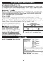
28 29 BRANCHEMENTS D’ALIMENTATION FONCTIONS Cet outil dispose d’un moteur électrique de précision. Il doit être branché à une ALIMENTATION DE 120 VOLTS, 60 HZ, CA SEULEMENT (COURANT RÉSIDENTIEL NORMAL). Ne faites pas fonctionner cet outil sur courant continu (CC). Une chute de tension importante cau...
Page 29 - FONCTIONS; APPRENEZ À CONNAÎTRE VOTRE SCIE À ONGLETS COMBINÉE
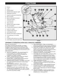
29 FONCTIONS Reportez-vous à la figure 1. Pour utiliser cet outil en toute sécurité, vous devez comprendre les informations fournies dans ce guide d’utilisation, ainsi que le projet que vous tentez. Avant d’utiliser ce produit, prenez le temps de vous familiariser avec toutes ses caractéristiques de...
Page 31 - MONTAGE ET TRANSPORT
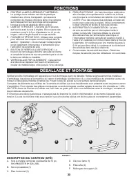
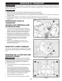
31 MONTAGE ET TRANSPORT AVERTISSEMENT : Pour assurer un fonctionnement sûr et précis, cette scie doit être montée sur une surface stable et plane comme un établi. Pour monter l'outil sur une surface stable, reportez-vous à la figure 5 et procédez comme suit :1. Localisez les quatre trous de montage ...
Page 32 - MONTAGE; INSTALLER LE SAC À POUSSIÈRE; RALLONGES DE SUPPORT
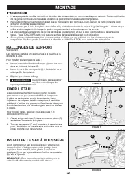
32 33 MONTAGE L'étau horizontal maintient la pièce contre le guide pour assurer une plus grande stabilité et il empêche la pièce de se déplacer vers la lame de scie. Selon l’opération de coupe et la taille de la pièce, il peut être préférable d’utiliser une presse en C au lieu de l'étau pour immobil...
Page 33 - INSTALLER LES PILES POUR; PRÉPARER VOTRE SCIE POUR L’UTILISATION; INSTALLER/REMPLACER LA LAME
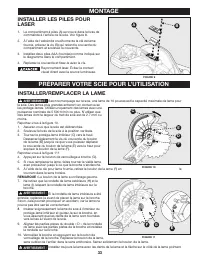
33 MONTAGE 1. Le compartiment à piles (A) se trouve dans le bras de commande à l’arrière de la scie. Voir figure 8. 2. À l’aide de l'extrémité cruciforme de la clé de lame fournie, enlevez la vis (B) qui retient le couvercle du compartiment et soulevez le couvercle. 3. Installez deux piles AAA (four...
Page 34 - ALIGNER LA LAME À LA TABLE
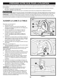
34 35 Reportez-vous à la figure 12.1. Débranchez la scie. 2. Abaissez le bras de la scie jusqu'à la position de transport et engagez la goupille de verrouillage pour le maintenir en place. 3. Tournez la poignée de verrouillage d'onglet (A). Placez la table de sorte que l’indicateur (B) de l'échelle ...
Page 35 - UTILISATION DU GUIDE LASER; POUR ENLEVER VOTRE MARQUE :
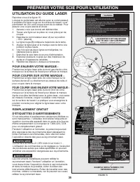
35 PRÉPARER VOTRE SCIE POUR L’UTILISATION UTILISATION DU GUIDE LASER POUR ENLEVER VOTRE MARQUE : POUR COUPER SUR VOTRE MARQUE : POUR COUPER SANS ENLEVER VOTRE MARQUE : REMPLACEMENT GRATUIT D'ÉTIQUETTES D'AVERTISSEMENTS Reportez-vous à la figure 15. Lorsque le guide laser est allumé (avec le commutat...
Page 36 - UTILISATION; VERROUILLAGE DE; COMMUTATEUR DE SÉCURITÉ
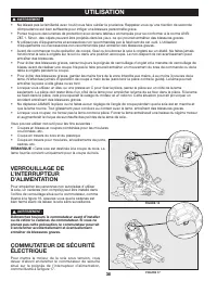
36 37 UTILISATION Vous pouvez utiliser cet outil pour les fins suivantes :• Coupes en biseau et coupes combinées pour les moulures couronnées, etc. • Coupe en travers du bois et du plastique• Coupe en travers pour moulures, encadrements de porte, cadres, etc. REMARQUE : Cette scie est destinée à la ...
Page 37 - FAIRE UNE COUPE EN GLISSIÈRE; COUPES EN BISEAU
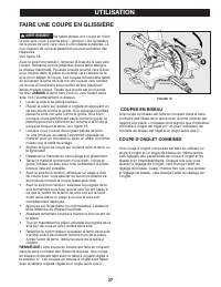
37 UTILISATION FAIRE UNE COUPE EN GLISSIÈRE AVERTISSEMENT : Ne faites jamais une coupe en tirant la scie vers vous. La lame peut « grimper » sur le dessus de la pièce et venir vers vous à une vitesse accélérée. Le non-respect de cet avertissement pourrait entraîner des blessures. Voir figure 18.Avec...
Page 38 - CONSEILS POUR LA DÉCOUPE ET LE SOUTIEN DES PIÈCES; CONSEILS POUR COUPE DE MOULURE COURONNÉE
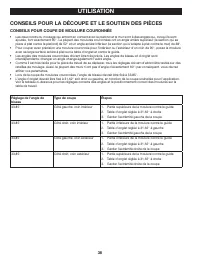
38 39 UTILISATION CONSEILS POUR LA DÉCOUPE ET LE SOUTIEN DES PIÈCES • Les deux bords du moulage qui entrent en contact avec le plafond et le mur sont à des angles qui, lorsqu'ils sont ajoutés, font exactement 90°. La plupart des moulures couronnées ont un angle arrière supérieur (la section qui se p...
Page 39 - COUPE DE MATÉRIAU DÉFORMÉ
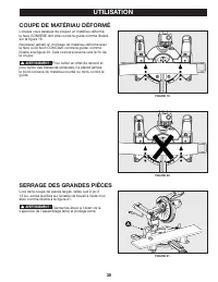
39 UTILISATION COUPE DE MATÉRIAU DÉFORMÉ SERRAGE DES GRANDES PIÈCES Lorsque vous essayez de couper un matériau déformé, la face CONVEXE doit être contre le guide comme illustré sur la figure 19. Ne placez jamais un morceau de matériau déformé avec la face ou le bord CONCAVE contre le guide, comme il...
Page 40 - SOUTIEN DES LONGUES PIÈCES; PIVOT DE BRAS
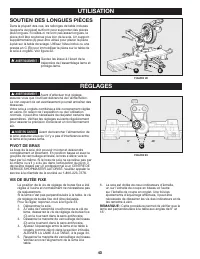
40 41 UTILISATION RÉGLAGES SOUTIEN DES LONGUES PIÈCES Dans la plupart des cas, les rallonges de table incluses (supports de pièce) suffiront pour supporter des pièces plus longues. Si celles-ci ne sont pas assez longues, la pièce doit être soutenue plus loin de la scie. Un support supplémentaire (A)...
Page 41 - RÉGLAGES; PIVOT POUR COUPE BISEAUTÉE; RÉGLAGE DU PARALLÈLE DU
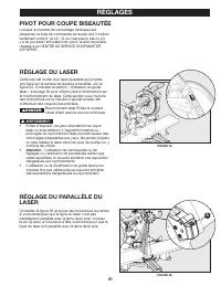
41 RÉGLAGES PIVOT POUR COUPE BISEAUTÉE Lorsque la manette de verrouillage de biseau est desserrée, le bras de commande de la scie doit s’incliner facilement entre 0° et 45°. Si ce n'est pas le cas ou s'il y a du jeu dans l’articulation du pivot, la scie devra être réparée à un CENTRE DE SERVICE SHOP...
Page 42 - RÉGLAGE DE L’ANGLE VERTICAL
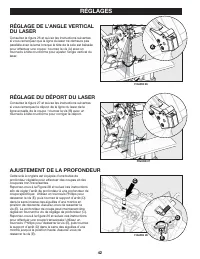
42 43 RÉGLAGES RÉGLAGE DE L’ANGLE VERTICAL DU LASER Consultez la figure 26 et suivez les instructions suivantes si vous remarquez que la ligne du laser ne demeure pas parallèle avec la lame lorsque la tête de la scie est baissée pour effectuer une coupe : tournez la vis (A) avec un tournevis à tête ...
Page 43 - ENTRETIEN; TENIR LA MACHINE PROPRE; REMPLACEMENT DES BROSSES
43 ENTRETIEN AVERTISSEMENT : Pour réduire les risques de blessures, éteignez l'appareil et débranchez-le de la source d'alimentation avant le nettoyage ou l'entretien, avant d'installer et de retirer tout accessoire et avant de faire des réglages lors de réparations. Un démarrage accidentel peut cau...
Page 44 - DÉMARRAGE IMPOSSIBLE; DÉPANNAGE; Garantie limitée de trois ans
44 45 DÉMARRAGE IMPOSSIBLE Si votre machine ne démarre pas, assurez-vous que les broches de la fiche du cordon sont bien en contact dans la prise. Aussi, vérifiez s’il y a des fusibles grillés ou des disjoncteurs ouverts dans votre ligne d'alimentation électrique. Si la scie ne démarre toujours pas,...
Page 45 - ASSISTANCE POUR PIÈCES, SERVICE OU GARANTIE; PIÈCES DE REMPLACEMENT
45 ASSISTANCE POUR PIÈCES, SERVICE OU GARANTIE PIÈCES DE REMPLACEMENT ENTRETIEN ET RÉPARATIONS REMPLACEMENT GRATUIT D'ÉTIQUETTES D'AVERTISSEMENTS Les seules pièces remplaçables par l’utilisateur sur cet outil sont: 1) Lame de scie 2) Brosses à moteur Toutes les autres pièces non listées ci-dessus do...
Page 47 - ÍNDICE; INSTRUCCIONES DE SEGURIDAD IMPORTANTES; LOGOTIPOS DE SEGURIDAD
47 ÍNDICE INSTRUCCIONES DE SEGURIDAD IMPORTANTES ........... 47LOGOTIPOS DE SEGURIDAD ................................................ 47REGLAS DE SEGURIDAD GENERALES PARA LAS HERRA - MIENTAS MOTORIZADAS ...................................................... 48REGLAS DE SEGURIDAD DE LA SIERRA INGLET...
Page 48 - No seguir todas las instrucciones detalladas a continuación
48 49 REGLAS DE SEGURIDAD GENERALES PARA LAS HERRAMIENTAS MOTORIZADAS ADVERTENCIA: Lea todas las advertencias de seguridad, instrucciones, ilustraciones y especificaciones suministradas con esta herramienta motorizada. No seguir todas las instrucciones detalladas a continuación podría provocar desca...
Page 49 - INSTRUCCIONES DE SEGURIDAD PARA LAS SIERRAS INGLETADORAS
49 REGLAS DE SEGURIDAD GENERALES PARA LAS HERRAMIENTAS MOTORIZADAS INSTRUCCIONES DE SEGURIDAD PARA LAS SIERRAS INGLETADORAS e. que no están familiarizadas con la herramienta motorizada o sus instrucciones utilicen la herramienta motorizada. Las herramientas motorizadas son peligrosas en las manos de...
Page 50 - CONEXIONES DE ALIMENTACIÓN; AISLAMIENTO DOBLE; PROPOSICIÓN DE CALIFORNIA 65
50 51 CONEXIONES DE ALIMENTACIÓN Debe usarse un circuito eléctrico independiente para las máquinas. Este circuito no debe ser menor a un hilo #12 y debe protegerse con un fusible de acción retardada de 15 amperes. Si se utiliza un cable de extensión, utilice únicamente cables de extensión de 3 alamb...
Page 51 - CONEXIÓN ELÉCTRICA
51 CONEXIONES DE ALIMENTACIÓN CARACTERÍSTICAS Esta herramienta posee un motor eléctrico construido a precisión. Se lo deberá conectar a una FUENTE DE ALIMENTACIÓN DE CA DE 120 VOLTIOS Y 60 ÚNICAMENTE (CORRIENTE HOGAREÑA NORMAL). No utilice esta herramienta con corriente continua (CC). Una caída sign...
Page 52 - CARACTERÍSTICAS; CONOZCA SU SIERRA INGLETADORA COMPUESTA
52 53 CARACTERÍSTICAS Consulte la Figura 1. El uso de esta herramienta de forma segura exige que comprenda la información incluida en este manual de operario, así como el proyecto que está intentando llevar a cabo. Antes de utilizar este producto, familiarícese con todas las funciones y reglas de se...
Page 54 - MONTAJE Y TRANSPORTE
54 55 ADVERTENCIA: A fin de garantizar un funcionamiento seguro y precioso, se deberá colocar la sierra sobre una superficie estable y nivelada, como, por ejemplo, un banco de trabajo. Para colocar la herramienta en una superficie estable, consulte la Figura 5 y realice lo siguiente: 1. Localice los...
Page 55 - ENSAMBLE; SUJECIÓN DE LA ABRAZADERA; EXTENSIONES DE APOYO
55 ENSAMBLE La abrazadera de fijación horizontal permite asegurar la pieza de trabajo a la guía tope para proporcionar más estabilidad y evitar que la pieza de trabajo se levante hacia la hoja de la sierra. En función de la operación de corte y el tamaño de la pieza de trabajo, puede que sea más rec...
Page 56 - PREPARACIÓN DE LA SIERRA PARA SU USO; INSTALACIÓN/REEMPLAZO DE LA HOJA
56 57 PREPARACIÓN DE LA SIERRA PARA SU USO INSTALACIÓN/REEMPLAZO DE LA HOJA ADVERTENCIA: Según las indicaciones de la sierra, una hoja de 10" es la capacidad máxima para hojas de la sierra. Las hojas más grandes entrarán en contacto con las protecciones de la hoja. Solo utilice hojas que tengan ...
Page 57 - ALINEACIÓN DE LA HOJA CON
57 Consulte la Figura 12.1. Desenchufe la sierra. 2. Baje por completo el brazo de la sierra hasta la posición de transporte y coloque el pasador de bloqueo para fijarlo en su lugar. 3. Gire la manija de bloqueo de inglete (A). Coloque la tabla de forma tal que el indicador de escala de inglete (B) ...
Page 58 - USO DE LA GUÍA LÁSER; PARA ELIMINAR LA MARCA:
58 59 PREPARACIÓN DE LA SIERRA PARA SU USO USO DE LA GUÍA LÁSER PARA ELIMINAR LA MARCA: PARA CORTAR EN LA MARCA: PARA CORTAR SIN ELIMINAR LA MARCA: REEMPLAZO GRATIS DE LA ETIQUETA DE ADVERTENCIA Cuando el interruptor de la guía láser se coloca en la posición de activación, proyecta una luz roja sobr...
Page 59 - FUNCIONAMIENTO; BLOQUEO DEL INTERRUPTOR; DISPOSITIVO DE SEGURIDAD
59 FUNCIONAMIENTO Puede utilizar esta herramienta para los siguientes trabajos:• Corte biselado y corte compuesto para molduras tipo corona, etc. • Corte transversal de madera y plástico.• Corte transversal de molduras, revestimientos de puertas, marcos de cuadros, etc. NOTA: La hoja suministrada es...
Page 60 - CORTE DESLIZANTE; CORTES BISELADOS
60 61 FUNCIONAMIENTO CORTE DESLIZANTE ADVERTENCIA: Nunca realice un corte tirando de la sierra hacia usted. La hoja puede "trepar" sobre la parte superior de la pieza de trabajo y dirigirse a usted a una velocidad acelerada. No seguir esta advertencia podría provocar lesiones personales grav...
Page 61 - RECOMENDACIONES PARA CORTAR Y APOYAR LA PIEZA DE TRABAJO; RECOMENDACIONES PARA CORTAR MOLDURAS TIPO CORONA
61 FUNCIONAMIENTO RECOMENDACIONES PARA CORTAR Y APOYAR LA PIEZA DE TRABAJO • Los dos bordes de la moldura que hacen contacto con el techo y la pared están en ángulos que, cuando se combinan, equivalen a exactamente 90°. La mayoría de las molduras tipo corona tienen un ángulo posterior superior (la s...
Page 62 - CORTE DE MATERIAL COMBADO
62 63 FUNCIONAMIENTO CORTE DE MATERIAL COMBADO SUJECIÓN DE PIEZAS DE TRABAJO ANCHAS Al intentar cortar material combado, el lado CONVEXO deberá colocarse contra la guía tope, tal como se muestra en la Figura 19. Nunca coloque material combado con el lado o borde CÓNCAVO contra la guía tope, tal como...
Page 63 - APOYO DE PIEZAS DE TRABAJO; PIVOTE DEL BRAZO
63 FUNCIONAMIENTO AJUSTES APOYO DE PIEZAS DE TRABAJO LARGAS En la mayoría de los casos, las extensiones de la mesa incluidas (apoyos de las piezas de trabajo) serán suficientes para apoyar las piezas de trabajo más largas. Si no son lo suficientemente largas, la pieza de trabajo deberá apoyarse desd...
Page 64 - AJUSTES; PIVOTE DE BISELADO; AJUSTE PARA LOGRAR UN
64 65 AJUSTES PIVOTE DE BISELADO Con la perilla de bloqueo de bisel aflojada, el brazo de control de la sierra deberá inclinarse fácilmente desde 0° y 45°. Si esto no ocurre o si existe juego en el pivote, se deberá reparar la sierra en un CENTRO DE SERVICIO TÉCNICO AUTORIZADO DE SHOPMASTER. AJUSTE ...
Page 65 - AJUSTE DE DEPTH STOP; AJUSTE DEL ÁNGULO
65 Esta sierra de inglete está equipada con un tope de profundidad ajustable para realizar cortes y cortes no transversales.Consulte la Figura 28 y siga estas instrucciones para ajustar el tope de profundidad a una profundidad de corte específica: Utilice un destornillador Phillips para aflojar el t...
Page 66 - MANTENIMIENTO; MANTENGA LIMPIA LA HERRAMIENTA; REEMPLAZO DE LAS ESCOBILLAS
66 67 MANTENIMIENTO ADVERTENCIA: Para reducir el riesgo de lesiones, apague la unidad y desconéctela de la fuente de alimentación, antes de limpiar o realizar el mantenimiento, instalar y extraer accesorios, antes de ajustar y al realizar reparaciones. Un arranque accidental puede provocar una lesió...
Page 67 - LA SIERRA NO ARRANCA; RESOLUCIÓN DE PROBLEMAS
67 LA SIERRA NO ARRANCA Si su máquina no arranca, verifique que las clavijas del enchufe tengan un buen contacto con el tomacorriente. Asimismo, verifique que no haya fusibles fundidos o un disyuntor abierto en su línea de fuente de alimentación. Si la sierra sigue sin arrancar, comuníquese con el C...
Page 68 - ASISTENCIA PARA PIEZAS, SERVICIO O GARANTÍA; PIEZAS DE REEMPLAZO; Garantía limitada de 3 años
68 69 ASISTENCIA PARA PIEZAS, SERVICIO O GARANTÍA Todas las máquinas y accesorios SHOPMASTER están fabricados con los estándares de calidad más altos y su servicio técnico es realizado a través de una red de centros de servicio técnico autorizados de DELTA ® . Para obtener información adicional rela...