Samsung AC100RXADKG/EU - Manuals
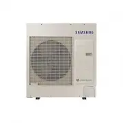
User Manual Samsung AC100RXADKG/EU


Summary
2 English Contents Safety Information 4 General information 4 Installing the unit 5 Power supply line, fuse or circuit breaker 6 Installation Procedure 7 Step 1 Choosing the installation location 7 Step 2 Fixing the outdoor unit in place 10 Step 3 Connecting the power cables, communication cable, an...
3 English Maintence Procedures 34 Performing the gas leak tests for repair 34 Decommissioning 34 Appendix 35 Troubleshooting 35 Technical specifications 36 COMMISSION DELEGATED REGULATION (EU) No 626/2011 i) 37 Correct Disposal of This Product (Waste Electrical & Electronic Equipment) (Applicabl...
4 Safety Information English Safety Inf ormation Safety Information WARNING • Hazards or unsafe practices that may result in severe personal injury or death. CAUTION • Hazards or unsafe practices that may result in minor personal injury or property damage. Carefully follow the precautions listed bel...
Samsung Air Conditioners Manuals
-
 Samsung AC026BNLDKG/EU
Installation Manual
Samsung AC026BNLDKG/EU
Installation Manual
-
 Samsung AC026BXAPKG/EU
User Manual
Samsung AC026BXAPKG/EU
User Manual
-
 Samsung AC035BNAPKG/EU
User Manual
Samsung AC035BNAPKG/EU
User Manual
-
Samsung AC035BNLDKG/EU
Installation Manual
-
 Samsung AC035HBMDKH/EU
User Manual
Samsung AC035HBMDKH/EU
User Manual
-
 Samsung AC035MN1DKH/EU
User Manual
Samsung AC035MN1DKH/EU
User Manual
-
Samsung AC035MN1DKH/EU
Installation Manual
-
 Samsung AC035MNNDKH/EU
User Manual
Samsung AC035MNNDKH/EU
User Manual
-
 Samsung AC035RN1DKG/EU
User Manual
Samsung AC035RN1DKG/EU
User Manual
-
Samsung AC035RN1DKG/EU
Installation Manual
-
Samsung AC035RNLDKG/EU
Installation Manual
-
 Samsung AC035RNMDKG/EU
User Manual
Samsung AC035RNMDKG/EU
User Manual
-
 Samsung AC035RNNDKG/EU
User Manual
Samsung AC035RNNDKG/EU
User Manual
-
 Samsung AC035TNXDKG/EU
User Manual
Samsung AC035TNXDKG/EU
User Manual
-
 Samsung AC052BN4PKG/EU
Installation Manual
Samsung AC052BN4PKG/EU
Installation Manual
-
 Samsung AC052BN6PKG/EU
Installation Manual
Samsung AC052BN6PKG/EU
Installation Manual
-
Samsung AC052BNAPKG/EU
User Manual
-
Samsung AC052BXAPKG/EU
User Manual
-
 Samsung AC052HBCDEH/EU
User Manual
Samsung AC052HBCDEH/EU
User Manual
-
 Samsung AC052HBJDEH/EU
User Manual
Samsung AC052HBJDEH/EU
User Manual