Samsung AC052BN4PKG/EU - Manuals
Samsung AC052BN4PKG/EU Air Conditioner – Installation Manual in PDF format online.
Manuals:
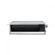
Installation Manual Samsung AC052BN4PKG/EU


Summary
2 English Contents Safety Information 3 Installation Procedure 5 Step 1 Checking and preparing accessories 5 Step 2 Choosing the installation location 5 Step 3 Optional: Insulating the body of the indoor unit 8 Step 4 Installing the indoor unit 9 Step 5 Purging inert gas from the indoor unit 10 Step...
3 English Sa fe ty In fo rm at io n Safety Information WARNING • Hazards or unsafe practices that may result in severe personal injury or death. CAUTION • Hazards or unsafe practices that may result in minor personal injury or property damage. • Carefully follow the precautions listed below because ...
4 Safety Information English Sa fe ty In fo rm at io n • Upon receipt, inspect the product to verify that it has not been damaged during transport. If the product appears damaged, DO NOT INSTALL it and immediately report the damage to the carrier or retailer (if the installer or the authorized techn...
Samsung Air Conditioners Manuals
-
 Samsung AC026BNLDKG/EU
Installation Manual
Samsung AC026BNLDKG/EU
Installation Manual
-
 Samsung AC026BXAPKG/EU
User Manual
Samsung AC026BXAPKG/EU
User Manual
-
 Samsung AC035BNAPKG/EU
User Manual
Samsung AC035BNAPKG/EU
User Manual
-
Samsung AC035BNLDKG/EU
Installation Manual
-
 Samsung AC035HBMDKH/EU
User Manual
Samsung AC035HBMDKH/EU
User Manual
-
 Samsung AC035MN1DKH/EU
User Manual
Samsung AC035MN1DKH/EU
User Manual
-
Samsung AC035MN1DKH/EU
Installation Manual
-
 Samsung AC035MNNDKH/EU
User Manual
Samsung AC035MNNDKH/EU
User Manual
-
 Samsung AC035RN1DKG/EU
User Manual
Samsung AC035RN1DKG/EU
User Manual
-
Samsung AC035RN1DKG/EU
Installation Manual
-
Samsung AC035RNLDKG/EU
Installation Manual
-
 Samsung AC035RNMDKG/EU
User Manual
Samsung AC035RNMDKG/EU
User Manual
-
 Samsung AC035RNNDKG/EU
User Manual
Samsung AC035RNNDKG/EU
User Manual
-
 Samsung AC035TNXDKG/EU
User Manual
Samsung AC035TNXDKG/EU
User Manual
-
 Samsung AC052BN6PKG/EU
Installation Manual
Samsung AC052BN6PKG/EU
Installation Manual
-
Samsung AC052BNAPKG/EU
User Manual
-
Samsung AC052BXAPKG/EU
User Manual
-
 Samsung AC052HBCDEH/EU
User Manual
Samsung AC052HBCDEH/EU
User Manual
-
 Samsung AC052HBJDEH/EU
User Manual
Samsung AC052HBJDEH/EU
User Manual
-
 Samsung AC052MNADKH/EU
User Manual
Samsung AC052MNADKH/EU
User Manual