Page 3 - GENERAL SAFETy RULES; READ ALL INSTRUCTIONS
3 — English GENERAL SAFETy RULES WARNING: Read and understand all instructions. Failure to follow all instructions listed below, may result in electric shock, fire and/or serious personal injury. READ ALL INSTRUCTIONS KNOW yOUR POWER TOOL. Read the operator’s manual carefully. Learn the saw’s appl...
Page 5 - SyMBOL; SyMBOLS
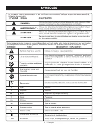
5 — English The following signal words and meanings are intended to explain the levels of risk associated with this product. SyMBOL SIGNAL MEANING DANGER: Indicates an imminently hazardous situation, which, if not avoided, will result in death or serious injury. WARNING: Indicates a potentially haza...
Page 6 - ELECTRICAL; ELECTRICAL CONNECTION; SPEED AND WIRING; ExTENSION CORDS
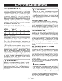
6 — English ELECTRICAL ELECTRICAL CONNECTION This tool is powered by a precision built electric motor. It should be connected to a power supply that is 120 V, AC only (normal household current), 60 Hz. Do not operate this tool on direct current (DC). A substantial voltage drop will cause a loss of p...
Page 7 - POSITION OF THE TILE SAW; FEATURES; KNOW yOUR TILE SAW
7 — English the saw to the outlet. The “drip loop” is that part of the cord below the level of the outlet, or the connector if an extension cord is used, to prevent water traveling along the cord and coming in contact with the outlet.If the plug or outlet does get wet, DO NOT unplug the cord. Discon...
Page 8 - ASSEMBLy; INSTALLING THE TILE CUTTING WHEEL
8 — English UNPACKING See Figure 4, page 14. This product requires assembly. Carefully lift the saw from the carton and place on a level work surface. WARNING: Do not use this product if any parts on the Loose Parts List are already assembled to your product when you unpack it. Parts on this list ...
Page 9 - OPERATION
9 — English INSTALLING THE SPLASH HOOD See Figure 6 - 7, page 14. Remove bevel table. Install the L-shaped splash hood bracket into the lip located under the table behind the wheel. Install the washers and screws into table and through splash hood bracket then tighten securely. NOTE: Be sure t...
Page 10 - MAKING CUTS; TO MAKE A CROSS CUT
10 — English OPERATION MAKING CUTS Always draw the line to be cut on the tile using a marker or grease pencil. If the tile is shiny and hard-to-mark, place masking tape on the tile and mark the tape. A common problem when cutting tile is straying from the marked line. Once you’ve strayed from the ma...
Page 11 - TO MAKE A MITER CUT; TO MAKE A BEVEL CUT
11 — English OPERATION Hold the material firmly against the miter guide and slide miter guide along rip guide. Feed the material into the cutting wheel. When the cut is made, turn the saw OFF. Wait for the cutting wheel to come to a complete stop before remov-ing any part of the material. TO MAK...
Page 12 - MAINTENANCE; GENERAL MAINTENANCE; FRENCH AND SPANISH LANGUAGE SECTIONS.
12 — English LUBRICATION All of the bearings in this tool are lubricated with a sufficient amount of high grade lubricant for the life of the unit under normal operating conditions. TILE CUTTING WHEEL For maximum performance and safety, it is recommended that you use the 7 in. cutting wheel provided...
Page 13 - TABLE DES MATIÈRES; GARANTIE
2 — Français Introduction ..................................................................................................................................................................... 2 Garantie ................................................................................................
Page 14 - RÈGLES DE SÉCURITÉ GÉNÉRALES; LIRE TOUTES LES INSTRUCTIONS
3 — Français RÈGLES DE SÉCURITÉ GÉNÉRALES TOUJOURS PORTER DES LUNETTES DE SÉCURITÉ À COQUES LATÉRALES. Les lunettes de vue ordinaires sont munies seulement de verres résistants aux impacts ; ce ne sont PAS des lunettes de sécurité. ASSUJETTIR LES PIÈCES. Dans la mesure du possible, utiliser des ...
Page 16 - SYMBOLES; SYMBOLE
5 — Français SYMBOLES Certains des symboles ci-dessous peuvent être utilisés sur l’outil. Veiller à les étudier et à apprendre leur signification. Une interprétation correcte de ces symboles permettra d’utiliser l’outil plus efficacement et de réduire les risques. Symbole d’alerte de sécurité SYMBOL...
Page 17 - CONNEXION ÉLECTRIQUE; VITESSE ET CÂBLAGE; CORDONS PROLONGATEURS; CARACTÉRISTIQUES ÉLECTRIQUES
6 — Français AVERTISSEMENT : Vérifier l’état des cordons prolongateurs avant chaque utilisation. Remplacer immédiatement tout cordon en-dommagé. Ne jamais utiliser un outil dont le cordon d’alimentation est endommagé, car tout contact avec la partie endommagée pourrait causer un choc électrique et d...
Page 18 - PLACER DE LA SCIE À CARREAUX; CARACTÉRISTIQUES
7 — Français CARACTÉRISTIQUES ÉLECTRIQUES Tout cordon endommagé doit être réparé ou remplacé immédiatement.Ce produit est pour l’usage sur un nominal 120 circuit de volt et a un fonder bouche similaire au bouchon illustré dans la figure 1, page 13. Seulement connecter le produit à une sortie ayant l...
Page 19 - INSTALLATION DE LA MEULE; DÉBALLAGE; ASSEMBLAGE
8 — Français AVERTISSEMENT : Ne pas brancher sur le secteur avant d’avoir terminé l’assemblage. Le non-respect de cet avertissement peut causer un démarrage accidentel, entraînant des bles-sures graves. INSTALLATION DE LA MEULE Voir la figure 5 page 14. AVERTISSEMENT : Cette scie n’utilise que des m...
Page 20 - INSTALLATION DU GUIDE LONGITUDINAL; UTILISATION; APPLICATIONS
9 — Français ASSEMBLAGE INSTALLATION DU CAPOT ANTI-ÉCLABOUS-SURES Voir les figures 6 et 7, page 14. Retirer la table de biseau. Installer le support en « L » du capot anti éclaboussures dans la lèvre située en dessous de la table et derrière la meule. Installer les rondelles et les vis dans la...
Page 21 - cOmmuTATEuR mARchE / ARRÊT; EXÉCUTION DE COUPES; POUR EFFECTUER UNE COUPE TRANSVERSALE
10 — Français cOmmuTATEuR mARchE / ARRÊT Voir la figure 11, page 15. Ce produit est équipé d’un commutateur avec dispositif de verrouillage intégré. Ce dispositif est conçu pour empêcher l’utilisation non autorisée et potentiellement dangereuse par des enfants ou personnes non compétentes. POUR METT...
Page 22 - POUR EFFECTUER UNE COUPE D’ONGLET; POUR EFFECTUER UNE COUPE EN L; POUR EFFECTUER UNE COUPE BISEAU
11 — Français Régler à l’angle désiré avec l’échelle d’angle et serrer solidement à l’aide du bouton Avant d’allumer la scie, s’assurer que le matériaux ne touche pas la meule à carreaux. Mettre le commutateur marche/arrêt en position de MARCHE (ON). Laissez le muele de coupe atteindre son r...
Page 23 - ENTRETIEN
12 — Français AVERTISSEMENT : Utiliser exclusivement des pièces Ryobi identiques à celles d’origine pour les réparations. L’usage de toute autre pièce pourrait créer une situation dangereuse ou endommager l’outil. AVERTISSEMENT : Toujours porter une protection oculaire certifiée conforme à la norme ...
Page 24 - ÍNDICE DE CONTENIDO; GARANTÍA
2 — Español Introducción ...................................................................................................................................................................... 2 Garantía ................................................................................................
Page 25 - REGLAS DE SEGURIDAD GENERALES; LEA TODAS LAS INSTRUCCIONES
3 — Español REGLAS DE SEGURIDAD GENERALES ADVERTENCIA: Lea y comprenda todas las instrucciones. El incumplimiento de las instrucciones señaladas abajo puede causar descargas eléctricas, incendios y lesiones serias. LEA TODAS LAS INSTRUCCIONES FAMILIARÍCESE CON SU HERRAMIENTA ELÉCTRICA. Lea cuidado...
Page 27 - SÍMBOLOS; SÍMBOLO SEÑAL
5 — Español Es posible que se empleen en esta herramienta algunos de los siguientes símbolos. Le suplicamos estudiarlos y aprender su significado. Una correcta interpretación de estos símbolos le permitirá utilizar mejor y de manera más segura la herramienta. SÍMBOLO NOMBRE DENOMINACIÓN / EXPLICACIÓ...
Page 28 - CONEXIÓN ELÉCTRICA; VELOCIDAD Y CABLEADO; INSTRUCCIONES DE CONEXIÓN A TIERRA; CABLES DE EXTENSIÓN; PARTES ELÉCTRICAS
6 — Español ADVERTENCIA: Inspeccione los cables de extensión cada vez antes de usarlos. Si están dañados, reemplácelos de inmediato. Nunca utilice la herramienta con un cable dañado, ya que si toca la parte da-ñada puede sufrir una descarga eléctrica, con las consecuentes lesiones graves. CONEXIÓN E...
Page 29 - POSICIONAR DEL SIERRA DE LOSAS; CARACTERÍSTICAS; FAMILIARÍCESE CON LA SIERRA DE LOSAS
7 — Español Consulte a un electricista calificado o técnico de servicio si no ha comprendido completamente las instrucciones de conexión a tierra o si no está seguro si la herramienta está bien conectada a tierra. Repare o reemplace de inmediato todo cordón dañado o gasta-do.Este producto se debe us...
Page 30 - DESEMPAQUETADO; ARMADO
8 — Español ADVERTENCIA: No conecte la unidad a la toma de corriente antes de terminar de armarla. De lo contrario, la unidad puede ponerse en mar-cha accidentalmente, con el consiguiente riesgo de lesiones graves. CAMBIO DEL DISCO DE TROCEADO DE AZULEJOS Vea la figura 5, página 14. ADVERTENCIA: La ...
Page 32 - INTERRUPTOR DE ENCENDIDO/APAGADO; FUNCIONAMIENTO; COUPES; PARA EFECTUAR CORTES TRANSVERSALES
10 — Español INTERRUPTOR DE ENCENDIDO/APAGADO Vea la figura 11, página 15. Esta sierra está equipada con un conjunto del interruptor de corriente dotado de cerradura de llave integrada. Esta característica tiene la finalidad de evitar el uso no autorizado y posiblemente peligroso por niños y otras p...
Page 33 - PARA EFECTUAR CORTES A INGLETE; PARA EFECTUAR CORTES EN L; PARA EFECTUAR CORTES EN BISEL
11 — Español FUNCIONAMIENTO Deje que la muela para cortar adquiera velocidad y espera para la rueda para mojar antes de mover la mesa de inglete para alimentar la pieza de trabajo a la muela. Sostenga firmemente la material contra la guía de borde al hilo y guía, y aváncela hacia la muela para c...
Page 34 - MANTENIMIENTO
12 — Español ADVERTENCIA: Al dar servicio a la unidad, sólo utilice piezas de repuesto Ryobi idénticas. El empleo de piezas diferentes puede causar un peligro o dañar el producto. ADVERTENCIA: Siempre use gafas de seguridad o anteojos protectores con protección lateral al usar herramientas eléctrica...
Page 40 - PARTS ANd SERVicE; • HOw tO OBtAIN REpLAcEMENt pARtS:; PiÈcES ET SERVicE
19 988000-0523-22-10 (REV:02) OPERATOR’S MANUAL / MANUEL D’UTILISATION /MANUAL DEL OPERADOR 7 in. TILE SAWSCIE À CARREAUx DE 178 mm (7 po)SIERRA DE LOSAS DE 178 mm (7 pulg.) WS721 • PARTS ANd SERVicE Prior to requesting service or purchasing replacement parts, please obtain your model and serial num...