Page 3 - GENERAL SAFETY RULES; ELECTRICAL SAFETY
3 GENERAL SAFETY RULES WARNING! READ AND UNDERSTAND ALL INSTRUCTIONS. Fail- ure to follow all instructions listed below, may result in electric shock, fire and/or serious personal injury. SAVE THESE INSTRUCTIONSWORK AREA Keep your work area clean and well lit. Cluttered benches and dark areas invi...
Page 4 - SERVICE
4 Hold tool by insulated gripping surfaces when per-forming an operation where the cutting tool may contact hidden wiring. Contact with a “live” wire will also make exposed metal parts of the tool “live” and shock the operator. Know your power tool. Read operator’s manual care-fully. Learn its a...
Page 5 - SYMBOLS; SYMBOL
5 SYMBOLS Some of the following symbols may be used on this product. Please study them and learn their meaning. Proper inter-pretation of these symbols will allow you to operate the product better and safer. SYMBOL NAME DESIGNATION/EXPLANATION V Volts Voltage A Amperes Current Hz Hertz Frequency (cy...
Page 6 - SAVE THESE INSTRUCTIONS
6 SYMBOLS SERVICE Servicing requires extreme care and knowledge and should be performed only by a qualified service technician. For service we suggest you return the product to the nearest AUTHORIZED SERVICE CENTER for repair. When servic- ing, use only identical replacement parts. WARNING: To avoid...
Page 7 - FEATURES; PRODUCT SPECIFICATIONS
7 FEATURES PRODUCT SPECIFICATIONS Motor ......................................................................................................................................................................18 Volt DCSwitch ................................................................................
Page 9 - ASSEMBLY; INSTALLING/REMOVING TRIMMING BITS
9 ASSEMBLY Fig. 2 INSTALLING/REMOVING TRIMMING BITS See Figures 2 - 3. If installing the bit for the first time, it can be installed once the collet nut is loose. If changing bits, the bit will easily slip from the collet after loosening the collet nut. Turn the switch to OFF and remove the batter...
Page 10 - OPERATION; APPLICATIONS; REMOVING THE BATTERY PACK
10 OPERATION WARNING: Do not allow familiarity with tools to make you care-less. Remember that a careless fraction of a second is sufficient to inflict serious injury. WARNING: Always wear safety goggles or safety glasses with side shields when operating tools. Failure to do so could re-sult in obje...
Page 11 - GRIPPING THE TRIMMER
11 OFF ON OPERATION WARNING: Battery tools are always in operating condition. There-fore, switch should always be off and the battery pack removed when not in use or carrying at your side. GRIPPING THE TRIMMER See Figure 5. The trimmer has a dual grip design that allows the operator to hold the tool...
Page 12 - OPERATING THE TRIMMER
12 OPERATION OPERATING THE TRIMMER Before starting the trimmer, with the battery pack discon-nected, make sure the bit is securely tightened in the collet and that the depth of cut is properly set. Never start the trimmer while the bit is in contact with the workpiece.After completing a cut, pull th...
Page 13 - SETTING DEPTH OF CUT
13 SETTING DEPTH OF CUT See Figure 9. Turn the switch off and remove the battery pack from the trimmer. Open the depth adjustment latch as indicated by the ar- row. Slide the motor housing section of the trimmer upward until the tip of the bit reaches the work surface. The depth of cut is zero...
Page 14 - OPTIONAL WOODWORKING SUB-BASE
14 R2 R2 R3 1 2 1/4 1/2 3/4 1 R2 R2 R3 1 2 1/4 1/2 3/4 1 OPERATION OPTIONAL WOODWORKING SUB-BASE Turn the P600 laminate trimmer into a trim router with the op-tional woodworking sub-base, Ryobi Part No. 200334001.The woodworking sub-base accessory with handles is con-venient when routing 4 in., 5 in...
Page 15 - ROUTING GROOVES IN A CIRCLE
15 OPERATION Fig. 12 ROUT GROOVE FROM RIGHT TO LEFT ROUTING GROOVES IN A CIRCLE See Figure 11. There are three holes marked R2", R2-1/2", and R3" on the woodworking sub-base. Each number represents a radius and may be used when cutting circular grooves that are 4 in., 5 in. or 6 in. in...
Page 16 - PROPER RATE OF FEED; FORCE FEEDING; TOO SLOW FEEDING
16 OPERATION Clean smooth trimming and edge shaping can be done only when the bit is revolving at a relatively high speed and is tak-ing very small bites to produce tiny, cleanly-severed chips. If the trimmer is forced to move forward too fast, the speed of the bit becomes slower than normal in rela...
Page 17 - DEPTH OF CUT
17 OPERATION Fig. 15 DEPTH OF CUT See Figure 15. Depth of cut affects the rate of feed and the quality of a cut. Using the proper depth of cut can lessen the possibility of damage to the trimmer motor and bit.A deeper cut requires a slower feed than a shallow one. Mak-ing a cut that is too deep will...
Page 18 - MAINTENANCE; BATTERIES
18 MAINTENANCE BATTERY PACK REMOVAL AND PREPARATION FOR RECYCLING To preserve natural resources, please r e c y c l e o r d i s p o s e o f b a t t e r i e s properly.This product uses nickel- cadmium and lithium-ion batteries. Local, state or federal laws may prohibit disposal of batteries in ordin...
Page 19 - ACCESSORIES
19 ACCESSORIES Look for these accessories at the service center: Woodworking Sub-base ..................................................................................................................................200334001 WARNING: Current attachments and accessories available for use with thi...
Page 20 - OPERATOR’S MANUAL; 8 VOLT TRIMMER; • SERVICE; • MODEL NUMBER
20 983000-600 7-27-10 (REV: 07) P600 OPERATOR’S MANUAL 18 VOLT TRIMMER P600 ONE WORLD TECHNOLOGIES, INC. 1428 Pearman Dairy Road, Anderson, SC 29625 Phone 1-800-525-2579 www.ryobitools.com • SERVICE Now that you have purchased your tool, should a need ever exist for repair parts or service, simply c...
Page 21 - MANUEL D’UTILISATION; ROGNEUSE 18 VOLTS; CONSERVER CE MANUEL POUR FUTURE RÉFÉRENCE
MANUEL D’UTILISATION ROGNEUSE 18 VOLTS P600 CONSERVER CE MANUEL POUR FUTURE RÉFÉRENCE Cette rogneuse a été conçue et fabriquée conformément aux strictes normes de fiabilité, simplicité d’emploi et sécurité d’utilisation. Correctement entretenue, elle vous donnera des années de fonctionnement robuste...
Page 22 - GARANTIE
2 Introduction ..................................................................................................................................................................... 2 Garantie ...........................................................................................................
Page 23 - RÈGLES DE SÉCURITÉ GÉNÉRALES; SÉCURITÉ ÉLECTRIQUE
3 RÈGLES DE SÉCURITÉ GÉNÉRALES AVERTISSEMENT ! LIRE ET VEILLER À BIEN COMPRENDRE TOUTES LES INSTRUCTIONS. Le non respect de toutes les instructions ci-dessous peut entraîner un choc électrique, un incendie et / ou des blessures graves. CONSERVER CES INSTRUCTIONSLIEU DE TRAVAIL Garder le lieu de tr...
Page 24 - DÉPANNAGE
4 Lorsque l’outil est utilisé pour un travail risquant de le mettre en contact avec des fils électriques cachés, le tenir par les surfaces de prise isolées. En cas de contact avec un fil sous tension, les parties métalliques exposées de l’outil seraient électrifées, exposant l’opérateur à un risqu...
Page 25 - SYMBOLES
5 Certains des symboles ci-dessous peuvent être utilisés sur produit. Veiller à les étudier et à apprendre leur signification. Une interprétation correcte de ces symboles permettra d’utiliser produit plus efficacement et de réduire les risques. SYMBOLE NOM DÉSIGNATION / EXPLICATION V Volts Tension A...
Page 26 - CONSERVER CES INSTRUCTIONS; SYMBOLE
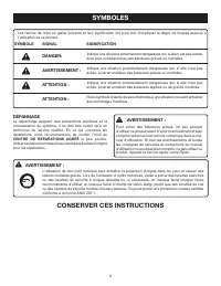
6 SYMBOLES DÉPANNAGE Le dépannage exigeant des précautions extrêmes et la connaissance du système, il ne doit être confié qu’à un technicien de service qualifié. En ce qui concerne les réparations, nous recommandons de confier l’outil au CENTRE DE RÉPARATIONS AGRÉÉ le plus proche. Utiliser exclusive...
Page 27 - CARACTÉRISTIQUES; FICHE TECHNIQUE
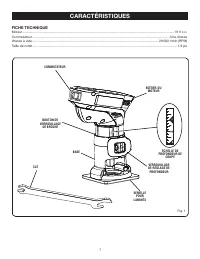
7 CARACTÉRISTIQUES FICHE TECHNIQUE Moteur .......................................................................................................................................................................18 V c.c.Commutateur .........................................................................
Page 29 - ASSEMBLAGE
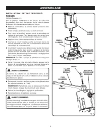
9 ASSEMBLAGE Fig. 2 INSTALLATION / RETRAIT DES FERS À ROGNER Voir les figures 2 et 3. Pour la première installation du fer, l’écrou du collet doit être desserré. Lors d’un changement de fer, celui-ci glissera facilement du collet après avoir desserré l’écrou. Mettre le commutateur en position d’ar...
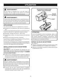
Page 30 - UTILISATION; INSTALLATION DU BLOC DE BATTERIES; RETRAIT DU BLOC DE BATTERIES
10 UTILISATION AVERTISSEMENT : Ne pas laisser la familiarité avec l’outil faire oublier la prudence. Ne pas oublier qu’une fraction de seconde d’inattention peut entraîner des blessures graves. AVERTISSEMENT : Toujours porter des lunettes étanches ou des lunettes de sé-curité à munies d’écrans latér...
Page 31 - TENUE DE LA ROGNEUSE; MISE EN MARCHE ET ARRÊT
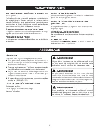
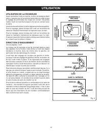
11 ARRÊT MARCHE UTILISATION AVERTISSEMENT : Les outils à batteries sont toujours en état de fonctionnement. C’est pourquoi le commutateur doit toujours être en position d’arrêt et le bloc de batteries retiré lorsque l’outil n’est pas en usage ou est transporté. TENUE DE LA ROGNEUSE Voir la figure 5....
Page 32 - UTILISATION DE LA ROGNEUSE
12 UTILISATION UTILISATION DE LA ROGNEUSE Avant de mettre l’outil en marche, le bloc de batteries étant retiré, s’assurer que le fer est bien serré dans le collet et que le réglage de profondeur de coupe est correct. Ne jamais mettre l’outil en marche lorsque le fer est en contact avec la pièce.Une ...
Page 33 - RÉGLAGE DE LA PROFONDEUR DE COUPE
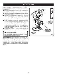
13 RÉGLAGE DE LA PROFONDEUR DE COUPE Voir la figure 9. Mettre le commutateur en position d’arrêt et retirer le bloc de batteries de l’outil. Ouvrir le verrouillage du réglage de profondeur, comme indiqué par la flèche. Faire glisser la portion boîtier du moteur de la rogneuse vers le haut jusq...
Page 34 - SEMELLE POUR BOIS EN OPTION
14 R2 R2 R3 1 2 1/4 1/2 3/4 1 R2 R2 R3 1 2 1/4 1/2 3/4 1 UTILISATION SEMELLE POUR BOIS EN OPTION La semelle pour bois en option, réf. Ryobi 200334001, permet de transformer la rogneuse en toupie de finition.La semelle pour bois permet de toupiller des rainures circulaires de 10, 13 et 15 cm (4, 5 et...
Page 35 - TOUPILLAGE DE RAINURES CIRCULAIRES
15 UTILISATION Fig. 12 TOUPILLER DE DROITE À GAUCHE TOUPILLAGE DE RAINURES CIRCULAIRES Voir la figure 11. La semelle pour travail du bois comporte trois trous marqués R2”, R2-1/2” et R3”. Chacun de ces chiffre représente un rayon permettant de toupiller des rainures circulaires de 10, 13 et 15 c...
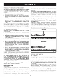
Page 36 - VITESSE D’ENGAGEMENT CORRECTE; AVANCE FORCÉE; AVANCE TROP LENTE
16 UTILISATION plus l’avance doit être lente. Si le bois est très dur, noueux, résineux ou humide, la vitesse d’avance doit être réduite encore davantage. Un toupillage ou profilage propre et net ne peut être obtenu que lorsque le fer tourne à relativement haute vitesse et mord légèrement, produisan...
Page 37 - PROFONDEUR DE COUPE
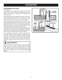
17 UTILISATION Fig. 15 PROFONDEUR DE COUPE Voir la figure 15. La profondeur de coupe affecte la vitesse d’avance et la qualité de la coupe. L’usage d’une profondeur de coupe correcte peut réduire les risques d’endommagement du moteur et du fer.Une coupe plus profonde demande une avance plus lente qu...
Page 38 - ENTRETIEN GÉNÉRAL; ENTRETIEN
18 RETRAIT ET PRÉPARATION DU BATTERIES POUR LE RECYCLAGE Pour préserver les ressources naturelles, les batteries doivent être recyclées ou éliminées selon une méthode appropriée. Ce produit utilise les piles de lithium-ion ou nickel-cadmium. Les réglementations locales ou gouvernementales peuvent in...
Page 39 - ACCESSOIRES
ACCESSOIRES Les accessoires ci-dessous sont en vente au centre de réparations : Semelle pour bois ............................................................................................................................................200334001 AVERTISSEMENT : Les outils et accessoires dispon...
Page 40 - • RÉPARATION; NUMÉRO DE MODÈLE
20 983000-600 7-27-10 (REV: 07) P600 MANUEL D’UTILISATION ROGNEUSE 18 VOLTS P600 ONE WORLD TECHNOLOGIES, INC. 1428 Pearman Dairy Road, Anderson, SC 29625 États-Unis Téléphone 1-800-525-2579 www.ryobitools.com AVERTISSEMENT : La poussière dégagée lors du ponçage, sciage, meulage, perçage de certains ...
Page 41 - MANUAL DEL OPERADOR; RECORTADORA DE 18 VOLTS; GUARDE ESTE MANUAL PARA FUTURAS CONSULTAS
MANUAL DEL OPERADOR RECORTADORA DE 18 VOLTS P600 GUARDE ESTE MANUAL PARA FUTURAS CONSULTAS Su recortadora ha sido diseñada y fabricada de conformidad con las estrictas normas de Ryobi para brindar fiabilidad, facilidad de uso y seguridad para el operador. Con el debido cuidado, le brindará muchos añ...
Page 42 - GARANTÍA
2 Introducción ..................................................................................................................................................................... 2 Garantía ...........................................................................................................
Page 43 - REGLAS DE SEGURIDAD GENERALES; GUARDE ESTAS INSTRUCCIONES; SEGURIDAD ELÉCTRICA; EMPLEO Y CUIDADO DE LA HERRAMIENTA
3 REGLAS DE SEGURIDAD GENERALES ¡ADVERTENCIA! LEA Y COMPRENDA TODAS LAS INSTRUCCIONES. El incumplimiento de las instrucciones señaladas abajo puede causar descargas eléctricas, incendios y lesiones corporales serias. GUARDE ESTAS INSTRUCCIONES ÁREA DE TRABAJO Mantenga limpia y bien iluminada el ár...
Page 44 - SERVICIO
4 Sujete la herramienta por las superficies aisladas de sujeción al efectuar una operación en la cual la herramienta de corte pueda entrar en contacto con cables ocultos. Con cualquier contacto de una herramienta de corte con un cable cargado se cargan las piezas metálicas expuestas de la herramie...
Page 45 - SÍMBOLOS
5 SÍMBOLOS Es posible que se empleen en este producto algunos de los siguientes símbolos. Le suplicamos estudiarlos y aprender su significado. Una correcta interpretación de estos símbolos le permitirá utilizar mejor y de manera más segura el producto. SÍMBOLO NOMBRE DENOMINACIÓN/EXPLICACIÓN V Volts...
Page 47 - CARACTERÍSTICAS; ESPECIFICACIONES DEL PRODUCTO
7 CARACTERÍSTICAS ESPECIFICACIONES DEL PRODUCTO Motor ........................................................................................................................................................ 18 volts, corr. cont.Interruptor ...............................................................
Page 48 - SUJECIÓN POR LA IZQUIERDA O DERECHA; ARMADO
8 CARACTERÍSTICAS FAMILIARÍCESE CON SU RECORTADORA DE LAMINADOS Vea la figura 1. El uso seguro que este producto requiere la comprensión de la información impresa en la herramienta y en el manual del operador así como ciertos conocimientos sobre el proyecto a realizar. Antes de usar este producto, f...
Page 49 - MONTAJE Y DESMONTAJE DE LAS FRESAS
9 ARMADO Fig. 2 MONTAJE Y DESMONTAJE DE LAS FRESAS DE RECORTAR Vea las figuras 2 y 3. Si va a instalar la fresa por primera vez, puede instalarla una vez aflojada la tuerca del portaherramientas. Si va a cambiar la fresa, ésta sale fácilmente del portaherramientas después de aflojar la tuerca del mi...
Page 50 - FUNCIONAMIENTO; APLICACIONES; INSTALACIÓN DEL PAQUETE DE PILAS; REMOCIÓN DEL PAQUETE DE PILAS
10 FUNCIONAMIENTO ADVERTENCIA: No permita que su familarización con las herramientas lo vuelva descuidado. Tenga presente que un descuido de un instante es suficiente para causar una lesión grave. ADVERTENCIA: Cuando utilice herramientas, póngase siempre gafas de seguridad o anteojos protectores con...
Page 51 - SUJECIÓN DE LA RECORTADORA
11 FUNCIONAMIENTO ADVERTENCIA: Las herramientas de pilas siempre están en condiciones de funcionamiento. Por lo tanto, cuando no esté usándose o esté acarreándose la herramienta a un costado, el interruptor siempre debe estar en la posición de apagado y el paquete de pilas desmontado. SUJECIÓN DE LA...
Page 52 - UTILIZACIÓN DE LA RECORTADORA
12 FUNCIONAMIENTO UTILIZACIÓN DE LA RECORTADORA Antes de encender la recortadora, teniendo desconectado el paquete de pilas, asegúrese de que la fresa esté firmemente apretada en el portaherramientas y de que esté debidamente ajustada la profundidad de corte. Nunca encienda la recortadora con la fre...
Page 53 - AJUSTE DE LA PROFUNDIDAD DE CORTE
13 AJUSTE DE LA PROFUNDIDAD DE CORTE Vea la figura 9. Ponga el interruptor en apagado (OFF) y retire de la recortadora el paquete de pilas. Abra el pestillo de ajuste de profundidad, como indica la flecha. Deslice hacia arriba la sección del alojamiento del motor de la recortadora hasta que la...
Page 54 - SUBBASE OPTATIVA PARA CARPINTERÍA
14 R2 R2 R3 1 2 1/4 1/2 3/4 1 R2 R2 R3 1 2 1/4 1/2 3/4 1 FUNCIONAMIENTO SUBBASE OPTATIVA PARA CARPINTERÍA La recortadora P600 puede convertirse en una fresadora de ornamentación con la subbase optativa para carpintería, pieza Ryobi núm. 200334001.La subbase optativa con mangos para carpintería es út...
Page 55 - FRESADO DE RANURAS EN CÍRCULO
15 FUNCIONAMIENTO Fig. 12 FRESE LA RANURA AVANZANDO DE DERECHA A IZQUIERDA FRESADO DE RANURAS EN CÍRCULO Vea la figura 11. Hay tres agujeros con las marcas R2”, R2-1/2” y R3” en la subbase para carpintería. Cada número representa un radio y puede usarse al cortar ranuras circulares de 10,2 cm (4 p...
Page 56 - VELOCIDAD DE AVANCE CORRECTA; AVANCE FORZADO
16 FUNCIONAMIENTO la pieza de trabajo. Cuanto más grande es la fresa o más profundo el corte, mayor será la lentitud de avance de la recortadora. Si la madera es muy dura, nudosa, gomosa o húmeda, debe bajarse la velocidad de la operación aún más. Un recortado y un moldurado de cantos limpio y unifo...
Page 57 - PROFUNDIDAD DEL CORTE
17 FUNCIONAMIENTO Fig. 15 PROFUNDIDAD DEL CORTE Vea la figura 15. La profundidad de corte afecta la velocidad de avance y la calidad del corte. Usando la profundidad de corte adecuada puede aminorarse la posibilidad de dañar el motor de la recortadora y la fresa.Un corte más profundo requiere una ve...
Page 58 - BATERÍAS; MANTENIMIENTO; MANTENIMIENTO GENERAL
18 BATERÍAS Este producto acepta baterías de iones de litio de 18 V y de níquel-cadmio de 18 V. El período de funcionamiento obtenible con cada carga depende del tipo de trabajo hecho.Las baterías de este producto están diseñadas para proporcionar una larga vida de servicio sin problemas. No obstant...
Page 59 - ACCESORIOS
ACCESORIOS Estos accesorios pueden encontrarse en el centro de servicio: Subbase para carpintería ................................................................................................................................200334001 ADVERTENCIA: Arriba se señalan los aditamentos y accesorios ...
Page 60 - NOTAS
Page 62 - • SERVICIO; • NÚMERO DE MODELO
22 983000-600 7-27-10 (REV: 07) P600 MANUAL DEL OPERADOR RECORTADORA DE 18 VOLTS P600 ONE WORLD TECHNOLOGIES, INC. 1428 Pearman Dairy Road, Anderson, SC 29625, EE.UU. Phone 1-800-525-2579 www.ryobitools.com • SERVICIO Ahora que ha adquirido esta herramienta, si alguna vez llega a necesitar piezas de...


 Ryobi SS630
User Manual
Ryobi SS630
User Manual
 Ryobi 18A-C06-734
User Manual
Ryobi 18A-C06-734
User Manual
 Ryobi 21AB454B734
User Manual
Ryobi 21AB454B734
User Manual
 Ryobi 41CD875A034
User Manual
Ryobi 41CD875A034
User Manual
 Ryobi 767R
User Manual
Ryobi 767R
User Manual
 Ryobi 2079R
User Manual
Ryobi 2079R
User Manual
 Ryobi 725R
User Manual
Ryobi 725R
User Manual
 Ryobi 890R
User Manual
Ryobi 890R
User Manual
 Ryobi 825R
User Manual
Ryobi 825R
User Manual
 Ryobi 96116000202
User Manual
Ryobi 96116000202
User Manual