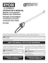
Page 6 - TABLE OF CONTENTS; TABLE DES MATIÈRES / ÍNDICE DE CONTENIDO; INTRODUCTION; INTRODUCTION / INTRODUCCIÓN
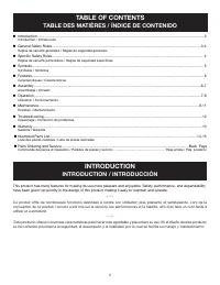
2 Introduction ...................................................................................................................................................................... 2 Introduction / Introducción General Safety Rules ................................................................
Page 7 - SAVE THESE INSTRUCTIONS; GENERAL SAFETY RULES; WHEN USING AN ELECTRIC POWER HEAD:
3 — English WARNING: Read and understand all instructions. Failure to fol- low all instructions listed below, may result in electric shock, fire, and/or serious personal injury. SAVE THESE INSTRUCTIONS Read these instructions and the instructions for the power head thoroughly before using pruner. ...
Page 8 - SPECIFIC SAFETY RULES
4 — English Kickback is a dangerous reaction that can lead to serious injury. Kickback may occur when the moving chain con-tacts an object at the upper portion of the tip of the guide bar or when the wood closes in and pinches the chain in the cut. Contact at the upper portion of the tip of the gu...
Page 9 - SYMBOLS; SYMBOL
5 — English SYMBOLS The following signal words and meanings are intended to explain the levels of risk associated with this product. SYMBOL SIGNAL MEANING DANGER: Indicates an imminently hazardous situation, which, if not avoided, will result in death or serious injury. WARNING: Indicates a potentia...
Page 10 - FEATURES; PRODUCT SPECIFICATIONS; ASSEMBLY; UNPACKING
6 — English FEATURES PRODUCT SPECIFICATIONS Bar length .................................................................. 10 in.Weight ..................................................................4-1/2 lbs. KNOW YOUR PRUNER ATTACHMENT See Figure 1. The safe use of this product requires an under...
Page 11 - APPLICATIONS
7 — English Align the button with the guide recess on the extension shaft coupler and slide the two shafts together. Rotate extension shaft until button locks into the positioning hole. NOTE: The attachment should only be operated with the blade in a vertical position. If the button does not rel...
Page 12 - OPERATION; LIMBING AND PRUNING
8 — English OPERATION Make a shallow first cut (1/4 of limb diameter) on the underside of the limb close to the main limb or trunk. Make a second cut from the top side of the limb outboard from the first cut. Make a final cut close to trunk. �NOTE: For second and final cuts (from top of limb o...
Page 13 - GENERAL MAINTENANCE; MAINTENANCE
9 — English WARNING: When servicing, use only identical replacement parts. Use of any other parts may create a hazard or cause product damage. WARNING: Always wear eye protection with side shields marked to comply with ANSI Z87.1, as well as hearing and head protection, when operating this equipment...
Page 14 - CHAIN TENSION; CHAIN OILER
10 — English MAINTENANCE WARNING: The chain should never turn at idle when using a gas power head. Turn the idle speed screw “T” counter-clockwise to reduce the idle RPM and stop the chain, or contact a service dealer for adjustment and discontinue use until the repair is made. Serious personal inju...
Page 15 - ATTACHING THE STORAGE HANGER
11 — English MAINTENANCE CAUTION: Dull or improperly sharpened chain can cause excessive engine or motor speed during cutting, which may result in severe engine or motor damage. ATTACHING THE STORAGE HANGER See Figure 24. There are two ways to hang the attachment for storage. To use the hanger cap...
Page 16 - TROUBLESHOOTING
12 — English Problem Possible Cause Solution B a r a n d c h a i n r u n n i n g h o t a n d smoking. Check chain tension for overtight condition. Chain oil tank empty. Tension chain. Refer to Chain Ten- sion earlier in this manual. Check oil tank. Chain tension too tight. Check guide bar and chain ...
Page 17 - WARRANTY; LIMITED WARRANTY STATEMENT
13 — English WARRANTY LIMITED WARRANTY STATEMENT Techtronic Industries North America, Inc., warrants to the original retail purchaser that this RYOBI ® brand outdoor product is free from defect in material and workmanship and agrees to repair or replace, at Techtronic Industries North America, Inc.’...
Page 18 - CONSERVER CES INSTRUCTIONS; RÈGLES DE SÉCURITÉ GÉNÉRALES
3 — Français AVERTISSEMENT : Lire et veiller à bien comprendre toutes les instructions. Le non-respect de toutes les instructions ci-dessous peut entraîner un choc électrique, un incendie et/ou des blessures graves. CONSERVER CES INSTRUCTIONS Lire attentivement ces instructions et celles du moteur...
Page 19 - RÈGLES DE SÉCURITÉ PARTICULIÈRES
4 — Français RÈGLES DE SÉCURITÉ PARTICULIÈRES Le rebond est une réaction dangereuse pouvant causer des blessures graves. Le rebond se produit lorsque la chaîne en rotation heurte un objet dans la partie supérieure de l’extrémité du guide ou lorsque l’entaille se referme et pince la chaîne dans le ...
Page 20 - SYMBOLES
5 — Français Les termes de mise en garde suivants et leur signification ont pour but d’expliquer le degré de risques associé à l’utilisation de ce produit. SYMBOLE SIGNAL SIGNIFICATION DANGER : Indique une situation extrêmement dangereuse qui, si elle n’est pas évitée, aura pour conséquences des ble...
Page 21 - CARACTÉRISTIQUES; FICHE TECHNIQUE; ASSEMBLAGE; DÉBALLAGE; LISTE DE CONTRÔLE D’EXPÉDITION
6 — Français CARACTÉRISTIQUES FICHE TECHNIQUE Longueur du guide .....................................254 mm (10 po)Poids ........................................................2,0 kg (4-1/2 lbs) APPRENDRE À CONNAÎTRE L’ACCESSOIRE D’ÉLAGAGE Voir la figure 1. L’utilisation sûre de ce produit exige un...
Page 22 - UTILISATION; PRÉPARATION POUR LA COUPE
7 — Français ASSEMBLAGE AVERTISSEMENT : Ne jamais installer ou ajuster un accessoire lorsque le moteur tourne. Ceci pourrait causer des blessures graves. Installation de l’accessoire : Débrancher le fil de la bougie ou débrancher de la prise secteur. Retirer l’anneau de suspension de l’arbre d’a...
Page 23 - MÉTHODE DE COUPE ÉLÉMENTAIRE; ÉBRANCHAGE ET ÉMONDAGE; POSITION DE DÉPART
8 — Français UTILISATION Toujours maintenir une bonne prise lorsque le moteur tourne. Saisir fermement la poignée arrière avec la main droite et la poignée avant avec la main gauche. Tenir l’outil fermement, à deux mains. Toujours garder la main gauche sur la poignée avant et la main droite su...
Page 24 - ENTRETIEN GÉNÉRAL; ENTRETIEN
9 — Français AVERTISSEMENT : Pour les réparations, utiliser exclusivement des pièces de rechange identiques à celles d’origine. L’usage de toute autre pièce pourrait créer une situation dangereuse ou endommager l’outil. AVERTISSEMENT : Toujours porter une protection oculaire avec écrans latéraux cer...
Page 25 - TENSION DE LA CHAÎNE; SYSTÈME DE LUBRIFICATION DE LA CHAÎNE
10 — Français ENTRETIEN RÉGLAGE DU RALENTI DE L’ENSEMBLE MOTEUR (ENSEMBLES MOTEURS À ESSENCE UNIQUEMENT) Si la chaîne tourne lorsque le moteur est au ralenti, tourner la vis de ralenti du moteur de un ensemble moteur à essence. Tourner la vis de ralenti vers la gauche pour réduire le régime et arrêt...
Page 26 - COMMENT AFFÛTER LES DENTS; REMISAGE DE L’ACCESSOIRE
11 — Français COMMENT AFFÛTER LES DENTS Voir les figures 20 à 23. AVERTISSEMENT : Un affûtage incorrect de la chaîne accroît le risque de rebond. L’utilisation d’une chaîne endommagée peut causer de blessures graves. Veiller à limer toutes les dents aux angles spécifiés et à la même longueur, car un...
Page 27 - DÉPANNAGE; TIREZ LE MEILLEUR PARTI DE VOTRE ACHAT!
12 — Français Problème Cause possible Solution Le guide et la chaîne chauffent et fument. Regarder si la chaîne est trop tendue. Réservoir d’huile vide. Tendre la chaîne. Voir Tension de la chaîne , plus haut dans ce manuel. Vérifier le niveau d’huile de chaîne dans le réservoir. Le moteur tourne, m...
Page 28 - GARANTIE; ÉNONCÉ DE LA GARANTIE LIMITÉE
13 — Français GARANTIE ÉNONCÉ DE LA GARANTIE LIMITÉE Techtronic Industries North America, Inc., garantit à l’acheteur original que ce produit RYOBI ® est exempt de tous vices de matériaux ou de fabrication et s’engage à réparer ou remplacer gratuitement, à son choix, tout produit s’avérant défectueu...
Page 29 - GUARDE ESTAS INSTRUCCIONES; REGLAS DE SEGURIDAD GENERALES
3 — Español ADVERTENCIA: Lea y comprenda todas las instrucciones. El in- cumplimiento de las instrucciones señaladas abajo puede causar descargas eléctricas, incendios y lesiones serias. GUARDE ESTAS INSTRUCCIONES Lea detenidamente estas instrucciones y las instrucciones para su cabezal motor ante...
Page 30 - REGLAS DE SEGURIDAD ESPECÍFICAS
4 — Español El contragolpe es una reacción peligrosa que puede ocasionar lesiones graves. El contragolpe ocurre cuando la cadena en movimiento hace contacto con un objeto en la parte superior de la punta de la barra, o cuando la madera se cierra y pellizca la cadena de la sierra en el punto de cor...
Page 31 - SÍMBOLOS
5 — Español Las siguientes palabras de señalización y sus significados tienen el objeto de explicar los niveles de riesgo relacionados con este producto. SÍMBOLO SEÑAL SIGNIFICADO PELIGRO: Indica una situación peligrosa inminente, la cual, si no se evita, causará la muerte o lesiones serias. ADVERTE...
Page 32 - CARACTERÍSTICAS; ESPECIFICACIONES DEL PRODUCTO; ARMADO; DESEMPAQUETADO
6 — Español CARACTERÍSTICAS ESPECIFICACIONES DEL PRODUCTO Longitud de la barra ............................... 254 mm (10 pulg.)Peso ........................................................ 2,0 kg (4-1/2 lbs.) FAMILIARÍCESE CON EL ACCESORIO PARA PODAR Vea la figura 1. Para usar este producto con la ...
Page 33 - FUNCIONAMIENTO; USOS
7 — Español ARMADO ADVERTENCIA: Nunca una ni ajuste ningún accesorio mientras esté funcionando el cabezal motor. Si no se detiene el motor podría causar lesiones personales graves. Para instalar el accesorio: Desconecte el cable de la bujía o desconecte la unidad del suministro de corriente. Q...
Page 34 - PROCEDIMIENTO BÁSICO DE CORTE; DESRAMADO Y PODA; POSICIÓN PARA EMPEZAR
8 — Español FUNCIONAMIENTO Mantenga una sujeción adecuada de la sierra siempre que esté funcionando el motor. Con la mano derecha sujete firmemente el mango posterior mientras sujeta firmemente el mango delantero con la izquierda. Sujete la sierra firmemente con ambas manos. Siempre mantenga ...
Page 35 - MANTENIMIENTO; MANTENIMIENTO GENERAL
9 — Español MANTENIMIENTO ADVERTENCIA: Al dar servicio a la unidad, sólo utilice piezas de repuesto idénticas. El empleo de piezas diferentes puede causar un peligro o dañar el producto. ADVERTENCIA: Siempre póngase protección ocular con protección lateral con la marca de cumplimiento de la norma AN...
Page 36 - TENSIÓN DE LA CADENA; LUBRICADOR DE LA CADENA
10 — Español MANTENIMIENTO ADVERTENCIA: Verifique frecuentemente la tensión de la cadena cuando se opere la unidad. Nunca toque ni ajuste la cadena mientras esté funcionando el motor. La cadena de la sierra está sumamente afilada; siempre póngase guantes protectores al efectuar labores de mantenimie...
Page 37 - FORMA DE AFILAR LOS DIENTES DE CORTE
11 — Español MANTENIMIENTO Si los dientes de corte han tocado objetos duros como clavos y piedras, o han sido desgastados por el lodo o la arena presentes en la madera, permita que afilen la cadena en un establecimiento de servicio apropiado para la tarea. FORMA DE AFILAR LOS DIENTES DE CORTE Vea ...
Page 38 - CORRECCIÓN DE PROBLEMAS; ¡APROVECHE AL MÁXIMO SU COMPRA!
12 — Español Problema Causa posible Solución La barra y la cadena están muy calientes y despiden humo. Revise la tensión de la cadena para ver si es excesiva. Está vacío el tanque de aceite de la cadena. Tensión de la cadena. Consulte el apartado Tensión de la cadena , más arriba en este manual. Rev...
Page 39 - GARANTÍA
13 — Español GARANTÍA DECLARACIÓN DE LA GARANTÍA LIMITADA Techtronic Industries North America, Inc. garantiza al comprador original al menudeo que este producto de la marca RYOBI ® carece de defectos en los materiales y en la mano de obra, y acuerda reparar o remplazar, a la sola discreción de Techt...
Page 40 - ILLUSTRATED PARTS LIST; LISTE DES PIÈCES ILLUSTRÉES
14 ILLUSTRATED PARTS LIST LISTE DES PIÈCES ILLUSTRÉES LISTA DE PIEZAS ILUSTRADAS 1 26 2 3 4 5 6 7 8 9 11 24 23 27 28 29 30 32 33 31 21 20 19 18 17 16 15 14 10 22 12 13 25 34
Page 44 - TECHTRONIC INDUSTRIES NORTH AMERICA, INC.; OPERATOR’S MANUAL; MANUEL D’UTILISATION / MANUAL DEL OPERADOR; PRUNER ATTACHMENT; ACCESSOIRE D’ÉLAGAGE / ACCESORIO PARA PODAR; CALIFORNIA PROPOSITION 65
987000-3792-7-11 (REV:05) TECHTRONIC INDUSTRIES NORTH AMERICA, INC. 1428 Pearman Dairy Road, Anderson, SC 29625 USA 1-800-860-4050 • www.ryobitools.com • PARTS AND SERVICE Prior to requesting service or purchasing replacement parts, please obtain your model and serial number from the product data pl...