Page 3 - Save all warnings and instructions for future reference.; WORK AREA SAFETY; Keep work area clean and well lit.; ELECTRICAL SAFETY; Do not expose power tools to rain or wet conditions.; PERSONAL SAFETY; Dress properly. Do not wear loose clothing or; POWER TOOL USE AND CARE; GENERAL SAFETY RULES
3 - English WARNING: Read all safety warnings, instructions, illustrations and specifications provided with this power tool. Failure to follow all instructions listed below may result in electric shock, fire and/or serious injury. Save all warnings and instructions for future reference. The term “po...
Page 4 - SERVICE
4 - English GENERAL SAFETY RULES Keep cutting tools sharp and clean. Properly maintained cutting tools with sharp cutting edges are less likely to bind and are easier to control. Use the power tool, accessories and tool bits etc. in accordance with these instructions, taking into account the wor...
Page 5 - TABLE SAW SAFETY RULES; KICKBACK
5 - English TABLE SAW SAFETY RULES Provide auxiliary workpiece support to the rear and/or sides of the saw table for long and/or wide workpieces to keep them level. A long and/or wide workpiece has a tendency to pivot on the table’s edge, causing loss of control, saw blade binding and kickback. ...
Page 7 - SYMBOLS
7 - English SYMBOLS Some of the following symbols may be used on this tool. Please study them and learn their meaning. Proper interpretation of these symbols will allow you to operate the tool better and safer. SYMBOL NAME DESIGNATION/EXPLANATION Safety Alert Indicates a potential personal injury ha...
Page 8 - ELECTRICAL; DOUBLE INSULATION; ELECTRICAL CONNECTION; power supply that is 120 V, AC only (normal; POLARIZED PLUGS; Cord Length; POLARIZED
8 - English ELECTRICAL DOUBLE INSULATION Double insulation is a concept in safety in electric power tools, which eliminates the need for the usual three-wire grounded power cord. All exposed metal parts are isolated from the internal metal motor components with protecting insulation. Double insulate...
Page 9 - GLOSSARY OF TERMS
9 - English GLOSSARY OF TERMS Pilot Hole (drill presses and scroll saws) A small hole drilled in a workpiece that serves as a guide for drilling large holes accurately or for insertion of a scroll saw blade. Push Blocks (jointer planers) Device used to feed the workpiece over the jointer planer cutt...
Page 10 - FEATURES; PRODUCT SPECIFICATIONS
10 - English FEATURES PRODUCT SPECIFICATIONS Blade Arbor .............................................................. 5/8 in.Blade Diameter .......................................................... 10 in.Blade Tilt ................................................................. 0˚ - 45˚ Dado Ca...
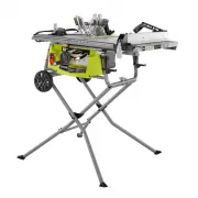
Page 11 - KNOW YOUR TABLE SAW
11 - English RIP FENCE STORAGE AREA MITER GAUGE STORAGE AREA BLADE GUARD STORAGE AREA DUST CHUTE PUSH STICK, RIVING KNIFE, AND BLADE WRENCH STORAGE AREA Fig. 3 KNOW YOUR TABLE SAW See Figure 2 - 3. The safe use of this product requires an understanding of the information on the tool and in this oper...
Page 12 - OPERATING COMPONENTS; SWITCH ASSEMBLY; SWITCH IN
12 - English FEATURES HEIGHT/BEVEL ADJUSTING HANDWHEEL - Located on the front of the saw, use this handwheel to lower and raise the blade for height adjustments or blade replacement. This handwheel also makes the adjustment for bevel angles easy. MITER GAUGE - The miter gauge aligns the wood for a c...
Page 13 - TOOLS NEEDED
13 - English The following tools (not included or drawn to scale) are needed for assembly and making adjustments: TOOLS NEEDED Fig. 5 FRAMING SQUARE PHILLIPS SCREWDRIVER FLATHEAD SCREWDRIVER SOCKET WRENCH, 13 mm AND 8 mm SOCKETS COMBINATION SQUARE C-CLAMPS 8 mm and 13 mm WRENCH
Page 14 - LOOSE PARTS
14 - English The following items are included with your table saw: A. Front Stand Leg (“A”) .........................................................1 B. Rear Stand Leg (“B”) ..........................................................1 C. Front Stand Leg (“C”) ...........................................
Page 15 - UNPACKING; MOUNTING HOLES; ASSEMBLY
15 - English UNPACKING This product requires assembly. Carefully lift saw from the carton and place it on a level work surface. NOTE: This tool is heavy. To avoid back injury, keep your knees bent and lift with your legs, not your back, and get help when needed. WARNING: Do not use this product if...
Page 16 - UNFOLDING THE STAND SUPPORTS; Locate the following parts:
16 - English LATCH ASSEMBLY UNFOLDING THE STAND SUPPORTS See Figure 7. NOTE: Do not use this leg stand with other equipment or for other purposes. NOTE: During shipping, the foam block between the saw’s housing and motor holds the stand leg bolts in place. Remove the foam block before assembling the...
Page 17 - INSTALLING THE CROSSPIECE; INSTALLING WHEELS ONTO THE STAND
17 - English CROSSPIECE PIVOT PLATE OUTER STAND SUPPORT BRACKET INNER STAND SUPPORT BRACKET BOLT Fig. 9 Locate the screw holes in the legs, near the pivot plates. Using a Phillips screwdriver, insert self-tapping screws through each of the holes. INSTALLING THE CROSSPIECE See Figure 10. Locate t...
Page 18 - INSTALLING THE SLIDING TABLE EXTENSION
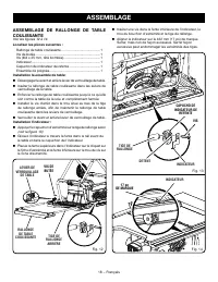
18 - English ASSEMBLY INSTALLING THE SLIDING TABLE EXTENSION See Figures 12 - 14. Locate the following parts: Sliding Table Extension ............................................... 1Stop Screw ................................................................. 1Screw (M4 x 25 mm, Truss Hd.) ............
Page 21 - IN “UP” POSITION; CHANGING RIVING KNIFE POSITIONS; To place in the “up” position for all through cutting:
21 - English Fig. 18 ASSEMBLY IN “UP” POSITION FOR THROUGH CUTTING IN “DOWN” POSITION FOR NON-THROUGH CUTTING RELEASE LEVER (LOCKED) RELEASE LEVER (UNLOCKED) CHANGING RIVING KNIFE POSITIONS See Figure 18. This saw is shipped with a riving knife that should be placed in the “down” position for non-th...
Page 22 - CHECKING SAW BLADE INSTALLATION; To tighten the blade:
22 - English ASSEMBLY CHECKING SAW BLADE INSTALLATION See Figure 19. NOTICE: To work properly, the saw blade teeth must point down toward the front of the saw. Failure to heed this warning could cause damage to the saw blade, the saw, or the workpiece. Unplug the saw. Remove the blade wrench fro...
Page 23 - INSTALLING THE BLADE GUARD; To install blade guard:
23 - English INCORRECT CORRECT ASSEMBLY INSTALLING THE BLADE GUARD See Figures 20 - 21. WARNING: Always install the blade guard onto the riving knife in the “up” position to provide proper blade coverage. Installing the guarding components onto the riving knife in any other position will prevent the...
Page 24 - To check alignment of the riving knife:
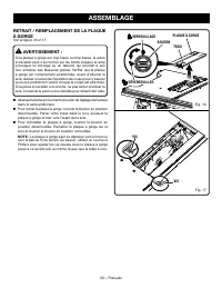
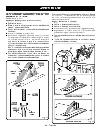
24 - English ASSEMBLY TO CHECK AND ALIGN THE RIVING KNIFE AND SAW BLADE See Figures 22 - 23. To check alignment of the riving knife: Unplug the saw. Raise the saw blade by turning the height/bevel adjusting handwheel clockwise. Adjust the bevel angle to 0° and lock the bevel locking lever. R...
Page 25 - TO MOVE THE SAW; STORING TABLE SAW ACCESSORIES
25 - English ASSEMBLY TO MOVE THE SAW See Figure 24. Close the leg stand as described earlier in the To open/ close (set-up/tear down) the leg stand section. Holding the leg stand firmly, pull the leg stand toward you until the leg stand and saw are balanced on the wheels like a handtruck. Pus...
Page 26 - OPERATION; APPLICATIONS
26 - English CAUSES OF KICKBACK Kickback can occur when the blade stalls or binds, kicking the workpiece back toward you with great force and speed. If your hands are near the saw blade, they may be jerked loose from the workpiece and may contact the blade. Obviously, kickback can cause serious inju...
Page 27 - CUTTING AIDS; To make a push stick:
27 - English OPERATION Clean the saw, blade guard, under the throat plate, and any areas where sawdust or scrap workpieces may gather. Keep blade guard, riving knife and ainti-kickback pawls in place and proper operation. The riving knife must be in alignment with the blade and the pawls must st...
Page 28 - WORKPIECE SUPPORTS; To attach the auxiliary fence to the rip fence:
28 - English JIG HANDLE STOP Fig. 32 3/4 in. 3-1/2 in. 21 in. JIG OPERATION Fig. 33 WORKPIECE SUPPORTS See Figure 31. When cutting with your table saw, make sure that the workpiece you are cutting is properly supported. Properly supporting the workpiece throughout the cutting process not only improv...
Page 29 - Making a Rip Cut; FEATHERBOARD; OFF; HOW TO MOUNT A FEATHERBOARD; Do not
29 - English Fig. 34 OPERATION To use a jig: Position the workpiece flat on the table with the edge flush against the jig and against the stop. Holding the jig handle and using a push block and/or push stick make the rip cut, see Making a Rip Cut later in this section. FEATHERBOARD A featherboar...
Page 30 - BEVEL RIP CUT; TYPES OF CUTS
30 - English OPERATION BEVEL RIP CUT RIP CUT CROSS CUT MITER CUT COMPOUND (BEVEL) MITER CUT BEVEL CROSS CUT 1 TYPES OF CUTS See Figure 36. There are six basic cuts: 1) the cross cut, 2) the rip cut, 3) the miter cut, 4) the bevel cross cut, 5) the bevel rip cut, and 6) the compound (bevel) miter cut...
Page 31 - TO CHANGE BLADE DEPTH
31 - English OPERATION TO CHANGE BLADE DEPTH See Figures 37 - 38. The blade depth should be set so that the outer points of the blade are higher than the workpiece by approximately 1/8 in. to 1/4 in. but the lowest points (gullets) are below the top surface. Turn the bevel lock lever to the right....
Page 32 - TO USE THE RIP FENCE; NEVER; To Check the Alignment
32 - English Fig. 42 OPERATION FRONT RAIL Fig. 41 Fig. 40 TO USE THE RIP FENCE See Figure 40 - 41. WARNING: To reduce the risk of injury, always make sure the rip fence is parallel to the blade before beginning any operation. NOTE: The rip fence included with your saw has a low fence. The low fence ...
Page 33 - TO USE THE SLIDING TABLE EXTENSION
33 - English OPERATION TO USE THE SLIDING TABLE EXTENSION See Figures 43 - 44. Increase the length of the saw table by using the table extension. Set the rip fence to 14 in. WARNING: The rip fence must be locked in the 14 in. position to ensure the accuracy of the secondary scale measurement and t...
Page 34 - TO USE THE MITER GAUGE; Cleaning the Riving Knife Lock Lever Plates
34 - English Fig. 45 Fig. 46 OPERATION TO USE THE MITER GAUGE See Figure 45. The miter gauge provides greater accuracy in angled cuts. For very close tolerances, test cuts are recommended.The miter gauge can be turned 60° to the right or left. Loosen the lock knob. With the miter gauge in the mi...
Page 35 - If the distances are different:; MAKING CUTS
35 - English OPERATION If the distances are different: Remove the blade guard and riving knife. Raise the blade by turning the height/bevel adjusting handwheel clockwise. Loosen the locking bolts by turning towards the left. NOTE: The bolts are located above the height/bevel adjusting handwheel ...
Page 36 - MAKING A CROSS CUT
36 - English OPERATION Fig. 50 CROSS CUT Fig. 49 Always place the workpiece against the face of the miter gauge body when making cuts. To prevent the workpiece from moving, you can attach a piece of sandpaper to the miter gauge body face. NOTE: It is recommended that you place the piece to be saved ...
Page 37 - To make repetitive cross cuts:; MAKING A RIP CUT
37 - English RIP CUT BLADE RIP FENCE PUSH STICK OPERATION To make repetitive cross cuts: A stop block can be used as a cut-off gauge to make repeti-tive cross cuts of the same length without having to mark the workpiece for each cut. The end of a stop block should always be in front of the blade. NE...
Page 38 - To make rip cuts narrower than 2 inches:
38 - English Turn the saw on. Position the workpiece flat on the table with the edge flush against the rip fence. Let the blade build up to full speed before feeding the workpiece into the blade. Using a push stick and/or push blocks, slowly feed the workpiece toward the blade. Stand slightly ...
Page 40 - MAKING A BEVEL RIP CUT
40 - English MAKING A BEVEL RIP CUT See Figure 57. WARNING: Make sure the blade guard assembly is installed and working properly to avoid serious personal injury. WARNING: The rip fence must be on the right side of the blade to avoid trapping the wood and causing kickback. Placement of the rip fence...
Page 41 - PLACE LEFT HAND ON
41 - English OPERATION MAKING A COMPOUND (BEVEL) MITER CUT See Figure 58. WARNING: Make sure the blade guard assembly is installed and working properly to avoid possible serious injury. Remove the rip fence. Unlock the bevel locking lever. Adjust the bevel angle to the desired setting. Lock ...
Page 42 - MAKING A LARGE PANEL CUT; SUPPORT
42 - English MAKING A LARGE PANEL CUT See Figure 59. Make sure the saw is properly secured to a work surface to avoid tipping from the weight of a large panel. WARNING: Make sure the blade guard assembly is installed and working properly to avoid possible serious injury. WARNING: Never make freehand...
Page 43 - MAKING A NON-THROUGH CUT; BLADE GUARD
43 - English OPERATION Fig. 60 MAKING A NON-THROUGH CUT See Figure 60. Non-through cuts (made with a standard 10 in. blade) can be made with the grain (ripping) or across the grain (cross cut). The use of a non-through cut is essential to cutting grooves, rabbets, and dadoes. This is the only type c...
Page 44 - DADO CUT; MAKING A DADO CUT
44 - English DADO CUT OPERATION MAKING A DADO CUT See Figure 61. An optional dado throat plate is required for this procedure (see the Accessories section of this manual and check with the retailer where the table saw was purchased). All blades and dado sets must not be rated less than the speed of ...
Page 45 - ADJUSTMENTS; REPLACING THE BLADE; DO NOT; To install a standard blade:
45 - English ADJUSTMENTS WARNING: Before performing any adjustment, make sure the tool is unplugged from the power supply and the top button on the switch is not depressed. Failure to heed this warning could result in serious personal injury. To avoid unnecessary set-ups and adjustments, a good prac...
Page 46 - To Set the; TO SET THE BEVEL INDICATOR AND BEVEL STOPS AT
46 - English Fig. 66 ADJUSTMENTS After installation, adjust the rip scale indicator to account for the kerf and thickness of the blade. Refer to To Set the Rip Fence Scale Indicator to the Blade in the Operation section of this manual. In cutting operations, the scale will be set to the side of the ...
Page 48 - GENERAL MAINTENANCE; do not; MAINTENANCE; LUBRICATION; LOCK
48 - English WARNING: When servicing, use only identical replacement parts. Use of any other parts may create a hazard or cause product damage. WARNING: Always wear eye protection with side shields marked to comply with ANSI Z87.1 during product operation. If operation is dusty, also wear a dust mas...
Page 49 - DUST CHUTE; To clean the dust chute:; TROUBLESHOOTING; Problem; DUST
49 - English ACCESSORIES Look for these accessories where you purchased this product or call 1-800-525-2579: Dado Throat Plate ........................................................................................................................................ 089240035708 WARNING: Current atta...
Page 50 - Adjusting the Blade Parallel to the
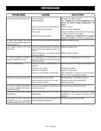
50 - English TROUBLESHOOTING Problem Cause Solution Cutting binds or burns work. Blade is dull.Blade is heeling. Work is fed too fast.Rip fence is misaligned.Workpiece is warped. Riving knife is out of alignment. Replace or sharpen blade.See Adjusting the Blade Parallel to the Miter Gauge Groove (Re...
Page 51 - SÉCURITÉ DU LIEU DE TRAVAIL; RÈGLES DE SÉCURITÉ GÉNÉRALES
3 − Français AVERTISSEMENT : Lire les avertissements de sécurité, les instructions et les précisions et consulter les illustrations fournis avec cet outil électrique. Le fait de ne pas se conformer à l’ensemble des consignes présentées ci-dessous risque d’entraîner des décharges électriques, un ince...
Page 52 - DÉPANNAGE; PROCÉDURES DE COUPE
4 − Français RÈGLES DE SÉCURITÉ GÉNÉRALES personnes n’ayant pas reçu des instructions adéquates, les outils sont dangereux. Entretenir les outils motorisés et accessoires. Vérifier qu’aucune pièce mobile n’est mal alignée ou bloquée, qu’aucune pièce n’est brisée et s’assurer qu’aucun autre problèm...
Page 53 - RÈGLES DE SÉCURITÉ SCIE À TABLE; REBOND
5 − Français RÈGLES DE SÉCURITÉ SCIE À TABLE ainsi peut provoquer un contact accidentel avec la lame en mouvement. Assurer un soutien auxiliaire pour la pièce à travailler à l’arrière ou sur les côtés de la scie à table pour les morceaux longs ou larges pour qu’ils restent de niveau. Les pièces à ...
Page 55 - SYMBOLES
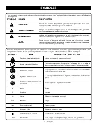
7 − Français SYMBOLES Certains des symboles ci-dessous peuvent être utilisés sur l’outil. Veiller à les étudier et à apprendre leur signification. Une interprétation correcte de ces symboles permettra d’utiliser l’outil plus efficacement et de réduire les risques. SYMBOLE NOM DÉSIGNATION / EXPLICATI...
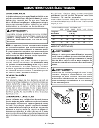
Page 56 - CARACTÉRISTIQUES ÉLECTRIQUES; DOUBLE ISOLATION; CONNEXIONS ÉLECTRIQUES; une alimentation 120 V,; FICHES POLARISÉES; Longueur; FICHE
8 − Français Fig. 1 CARACTÉRISTIQUES ÉLECTRIQUES DOUBLE ISOLATION La double isolation est un dispositif de sécurité utilisé sur les outils à moteur électriques, éliminant le besoin de cordon d’alimentation habituel à trois fils avec terre. Toutes les pièces métalliques exposées sont isolées des comp...
Page 57 - GLOSSAIRE
9 − Français GLOSSAIRE Trou pilote (perceuses à colonne et scie à découper) Petit trou pratiqué dans une pièce servant de guide pour assurer la précision d’un trou de plus grand diamètre ou pour l’insertion d’une lame de scie à découper. Blocs poussoirs (pour dégauchisseuses/raboteuses) Dispositifs ...
Page 58 - CARACTÉRISTIQUES; FICHE TECHNIQUE
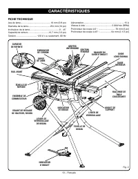
10 − Français CARACTÉRISTIQUES FICHE TECHNIQUE Axe de lame ................................................16 mm (5/8 po)Diamètre de la lame................................... 254 mm (10 po)Inclinaison de la lame .............................................. 0˚ - 45˚Capacité de rainure ...............
Page 59 - POUR SE FAMILIARISER AVEC LA SCIE À TABLE
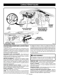
11 − Français POUR SE FAMILIARISER AVEC LA SCIE À TABLE Voir les figure 2 et 3. L’utilisation sûre de ce produit exige une compréhension des renseignements figurant sur l’outil et contenus dans le manuel d’utilisation, ainsi qu’une bonne connaissance du projet entrepris. Avant d’utiliser ce produit,...
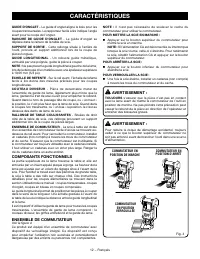
Page 60 - COMPOSANTS FONCTIONNELS; ENSEMBLE DE COMMUTATEUR
12 − Français CARACTÉRISTIQUES GUIDE D’ONGLET - Le guide d’onglet aligne le bois pour les coupes transversales. Le rapporteur facile à lire indique l’angle exact pour la coupe de l’onglet. RAINURE DE GUIDE D’ONGLET - Le guide d’onglet se déplace dans le rainure de la table de scie. SUPPORT DE SORTIE...
Page 61 - OUTILS NÉCESSAIRES
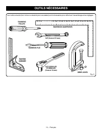
13 − Français Les outils suivants (non inclus ou dessiné pour escalader) sont nécessaires pour effectuer l’assemblage et les réglages : OUTILS NÉCESSAIRES Fig. 5 ÉQUERRE DE CHARPENTIER TOURNEVIS PHILLIPS TOURNEVIS PLAT CLÉ À DOUILLES ET DOUILLES (8 mm et 13 mm) ÉQUERRE COMBINÉE SERRE-JOINTS CLÉ (8 m...
Page 62 - PIÈCES DÉTACHÉES
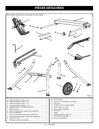
14 − Français Les articles suivant sont inclus avec la scie à table : A. Patte de support avant (« A ») ............................................1 B. Patte de support arrière (« B ») ..........................................1 C. Patte de support avant (« C ») .......................................
Page 63 - DÉBALLAGE; TROUS DE MONTAGE; ASSEMBLAGE
15 − Français DÉBALLAGE Ce produit doit être assemblé. Sortir la scie du carton avec précaution et la poser une un plan de travail stable. NOTE : Cet outil est lourd. Pour éviter des problèmes lombaires, garder les genous pliés, soulever avec les jambes, pas avec le dos et demander de l’aide lorsq...
Page 64 - DÉPLIAGE DU SUPPORT À PATTES
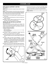
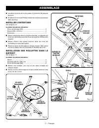
16 − Français ASSEMBLAGE DÉPLIAGE DU SUPPORT À PATTES Voir la figure 7. NOTE : Ne pas se stand à un usage autre que celui pour lequel il est conçu. NOTE : Pendant la livraison, le bloc de mousse entre le boîtier de la scie et le moteur tient les boulons des pattes du support en place. Retirer le blo...
Page 65 - INSTALLER L’ENTRETOISE
17 − Français ENTRETOISE ÉCROU DE BLOCAGE ÉCROU DE BLOCAGE BOULON Localiser les trous de vis du pattes, à proximité de plaques de pivot. À l’aide d’un tournevis Phillips, insérer les vis auto-taraudeuse dans les trous. INSTALLER L’ENTRETOISE Voir la figure 10. Localiser les pièces suivantes : Éc...
Page 67 - INSTALLER
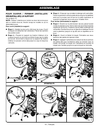
19 − Français ASSEMBLAGE P O U R O U V R I R / F E R M E R ( I N S TA L L E R / DÉSINSTALLER) LE SUPPORT Voir la figure 15. NOTE : Utiliser l’attache pour cordon au bout de la scie pour tenir le cordon hors du chemin lorsqu’on installe ou qu’on désinstalle la scie. Pour ouvrir (installer) le support...
Page 69 - LEVIER DE; EN « HAUT » POSITION POUR TOUT PAR TRAVERSANTE
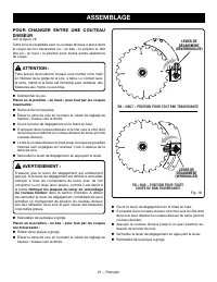
21 − Français ASSEMBLAGE LEVIER DE DÉGAGEMENT (VERROUILLÉE) POUR CHANGER ENTRE UNE COUTEAU DIVISEUR Voir la figure 18. Cette scie est expédiée avec le couteau diviseur a placé dans la coupe de non traversante ou « en bas » la position et doit être en.« en haut » la position pour toutes autres opérat...
Page 71 - INSTALLATION DE PROTÈGE-LAME
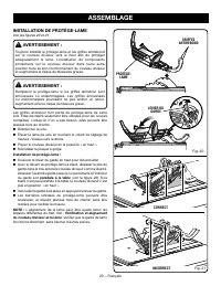
23 − Français ASSEMBLAGE INSTALLATION DE PROTÈGE-LAME Voir les figures 20 et 21. AVERTISSEMENT : Toujours installer le protège-lame et les griffes antirebond sur le couteau diviseur vers le haut afin de protéger adéquatement la lame. L’installation de composants protecteurs sur le couteau diviseur d...
Page 73 - POUR DÉPLACER LA SCIE
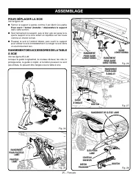
25 − Français ASSEMBLAGE POUR DÉPLACER LA SCIE Voir la figure 24. Fermer le support à pattes comme il est décrit à la partie Pour ouvrir / fermer (installer / désinstaller) le support dans cette section. Tenir fermement le support, puis le tirer vers soi jusqu’à ce que le support et la scie soie...
Page 74 - CAUSES DE REBONDS; UTILISATION
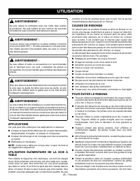
26 − Français modifier la fiche de quelque façon que ce soit. Voir la section Caractéristiques électriques de ce manuel. CAUSES DE REBONDS Un rebond peut se produire lorsque la lame se bloque ou se coince et propulse violemment la pièce à couper en direction de l’opérateur. Si les mains se trouvent ...
Page 75 - CONSEILS DE COUPE
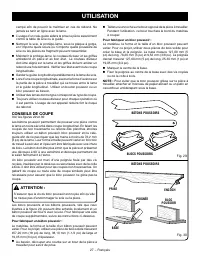
27 − Français UTILISATION campé afin de pouvoir la maîtriser en cas de rebond. Ne jamais se tenir en ligne avec la lame. L’usage d’un cale-guide aidera la prise la pièce assurément contre la table de scie ou le guide. Nettoyer la scie, le protège-lame, sous la plaque à gorge, et n’importe quels ...
Page 76 - SUPPORTS DE LA PIÈCE À TRAVAILLER
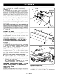
28 − Français UTILISATION SUPPORTS DE LA PIÈCE À TRAVAILLER Voir la figure 31. En coupant avec votre scie à table, veiller à ce que la pièce à couper soit correctement soutenue. Bien soutenir la pièce à travailler lors de la découpe permet non seulement d’améliorer la précision de coupe, mais aussi ...
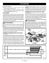
Page 77 - COMMENT FABRIQUER UNE CALE-GUIDE; COMMENT INSTALLER UNE CALE-GUIDE; POUSSOIR
29 − Français UTILISATION Pour utiliser sauteuse : Disposer la pièce plate sur la table avec l’éclat de bord contre la sauteuse et contre buteé. L’avoir la poignée de sauteuse et l’utilisation d’un bâton poussoir et/ou de bloc poussoir, voir ci-après la partie Coupe longitudinale dans cette sect...
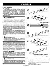
Page 78 - TYPES DE COUPE; COUPE LONGITUDINALE EN BISEAU
30 − Français UTILISATION TYPES DE COUPE Voir la figure 36. Il y a six principaux types de coupe : 1) coupe transversale, 2) coupe longitudinale, 3) coupe d’onglet, 4) coupe transversale en biseau, 5) coupe en long en biseau et 6) coupe d’onglet composé (en biseau). Toutes les autres coupes sont des...
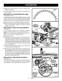
Page 79 - RÉGLAGE DE LA PROFONDEUR DE LAME
31 − Français UTILISATION Retirer les noeuds décollés à l’aide d’un marteau avant d’effectuer la coupe. Toujours utiliser un support adéquat sous une planche à la sortie de la scie. RÉGLAGE DE LA PROFONDEUR DE LAME Voir les figures 37 et 38. La profondeur de coupe doit être réglée pour que les p...
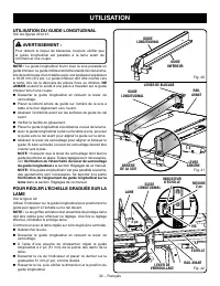
Page 80 - UTILISATION DU GUIDE LONGITUDINAL
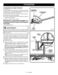
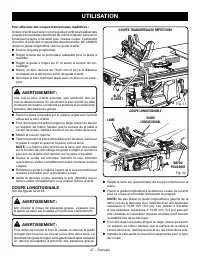
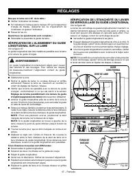
32 − Français UTILISATION UTILISATION DU GUIDE LONGITUDINAL Voir les figures 40 et 41. AVERTISSEMENT : Pour réduire le risque de blessures, toujours vérifier que le guide longitudinal est parallèle à la lame avant de commencer une coupe. NOTE : Le guide longitudinal fourni avec la scie possède un gu...
Page 82 - UTILISATION DU GUIDE D’ONGLET
34 − Français RÈGLE Fig. 45 Fig. 46 UTILISATION UTILISATION DU GUIDE D’ONGLET Voir la figure 45. Le guide d’onglet permet d’effectuer des coupes en biais de grande précision. Il est recommandé d’effectuer des coupes d’essai lorsque les tolérances sont réduites.Le guide d’onglet peut être tourné de 6...
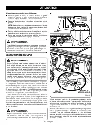
Page 83 - EXÉCUTION DE COUPES
35 − Français UTILISATION Si les distances mesurées sont différentes : Retirer la garde de lame, le couteau diviseur et griffes antirebond. Relever la lame au maximum en tournant le volant de réglage de hauteur / biseau vers la droite. Desserrer les boulons de verrouillage en tournant vers la ga...
Page 85 - COUPE LONGITUDINALE
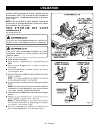
37 − Français UTILISATION GUIDE LONGITUDINAL Pour effectuer des coupes transversales répétitives : Un bloc d’arrêt peut servir comme guide d’arrêt pour réaliser des coupes transversales répétitives de même longueur sans avoir à marquer la pièce à travailler pour chaque coupe. L’extrémité d’un bloc d...
Page 88 - GUIDE
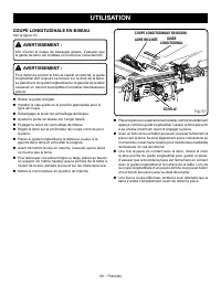
40 − Français COUPE LONGITUDINALE EN BISEAU Voir la figure 57. AVERTISSEMENT : Afin d’éviter le risque de blessures graves, s’assurer que la garde de lame est installée et fonctionne correctement. AVERTISSEMENT : Pour éviter de coincer le bois et causer un rebond, le guide longitudinal doit toujours...
Page 89 - PLACER LA MAIN GAUCHE
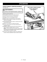
41 − Français UTILISATION COUPE D’ONGLET COMPOSÉ (EN BISEAU) Voir la figure 58. AVERTISSEMENT : Afin d’éviter le risque de blessures graves, s’assurer que la garde de lame est installée et fonctionne correctement. Retirer le guide longitudinal. Désengager le levier de verrouillage de biseau. A...
Page 90 - COUPE D’UNE PIÈCE DE GRANDE TAILLE; GUIDE LONGITUDINAL
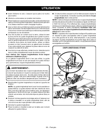
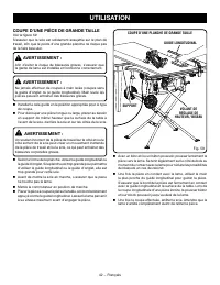
42 − Français COUPE D’UNE PIÈCE DE GRANDE TAILLE Voir la figure 59. S’assurer que la scie est solidement assujettie sur le plan de travail, afin que le poids d’une grande planche ne risque pas de la faire basculer. AVERTISSEMENT : Afin d’éviter le risque de blessures graves, s’assurer que la garde d...
Page 91 - COUPE NON TRAVERSANTE
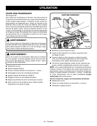
43 − Français UTILISATION COUPE NON TRAVERSANTE Voir la figure 60. Les coupes non traversantes (a fait avec une norme lame de 10 po) peuvent être effectuées avec le grain (longitudinale) ou contre le grain (transversale). L’utilisation d’une coupe non transversante est essentielle pour couper les ra...
Page 92 - EXÉCUTION D’UN RAINAGE; RAINAGE
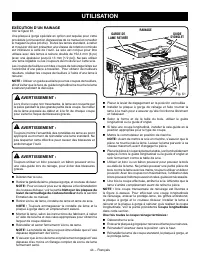
44 − Français GUIDE D’ONGLET UTILISATION EXÉCUTION D’UN RAINAGE Voir la figure 61. Une plaque à gorge spéciale en option est requise pour cette procédure (voir la section Accessoires de ce manuel et consulter le magasin le plus proche). Toutes les lames standard, à rainer et moulurer doivent présent...
Page 93 - RÉGLAGES; REMPLACEMENT DE LA LAME
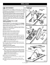
45 − Français RÉGLAGES AVERTISSEMENT : Avant d’effectuer tout réglage, s’assurer que l’outil est débranché et le bouton supérieur du commutateur n’est pas enfoncé. Le non-respect de cet avertissement pourrait entraîner des blessures graves. Pour éviter des ajustements inutiles, il est bon de vérifie...
Page 94 - ̊ VIS DE
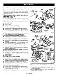
46 − Français RÉGLAGES Après l’installation, ajuster l’indicateur de l’échelle de refente pour tenir compte du trait et de l’épaisseur de la lame. Rapportez-vous à Pour régler l’échelle graduée sur la lame dans la section Utilisation dans ce manuel. Lors de la coupe, l’échelle doit être placée du cô...
Page 96 - ENTRETIEN GÉNÉRAL; ENTRETIEN; LUBRIFICATION
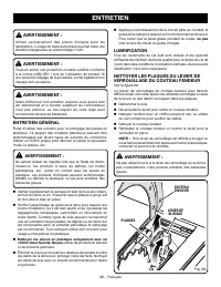
48 − Français AVERTISSEMENT : Utiliser exclusivement des pièces d’origine pour les réparations. L’usage de toute autre pièce pourrait créer une situation dangereuse ou endommager l’outil. AVERTISSEMENT : Toujours porter une protection oculaire certifiée conforme à la norme ANSI Z87.1 lors de l’utili...
Page 97 - CHUTE À COPEAUX; ACCESSOIRES; PROBLÈME; CHUTE À
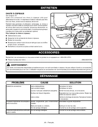
49 − Français ENTRETIEN CHUTE À COPEAUX Voir la figure 70. C e t t e s c i e c o m p re n d u n e c h u t e à c o p e a u x u t i l e p o u r débarrasser la sciure. Un aspirateur d’atelier ordinaire peut être fixé à la chute, située sous le dessous de la scie.Pendant des périodes d’utilisation prolo...
Page 99 - ÁREA DE TRABAJO; SEGURIDAD ELÉCTRICA; REGLAS DE SEGURIDAD GENERALES
3 − Español ADVERTENCIA: Lea todas las advertencias, instrucciones, ilustraciones y especificaciones proporcionadas con esta herramienta eléctrica. No seguir las instrucciones indicadas a continuación puede provocar descargas eléctricas, incendios o lesiones graves. Guarde todas las advertencias e i...
Page 100 - SERVICIO; PROCEDIMIENTOS DE CORTE
4 − Español REGLAS DE SEGURIDAD GENERALES que la reparen antes de usarla. Numerosos accidentes son causados por herramientas eléctricas mal cuidadas. Mantenga las herramientas de corte afiladas y limpias. Las herramientas de corte bien cuidadas y con bordes bien afilados, tienen menos probabilidad...
Page 101 - REGLAS DE SEGURIDAD SIERRA DE MESA; CONTRAGOLPE
5 − Español REGLAS DE SEGURIDAD SIERRA DE MESA Proporcione apoyo auxiliar para la pieza de trabajo en la parte trasera y los laterales de la mesa de la sierra cuando corte piezas largas o anchas, a fin de mantenerlas niveladas. Las piezas de trabajo largas o anchas tienden a pivotar con el borde d...
Page 103 - SÍMBOLOS
7 − Español SÍMBOLOS Es posible que se empleen en esta herramienta algunos de los siguientes símbolos. Le suplicamos estudiarlos y aprender su significado. Una correcta interpretación de estos símbolos le permitirá utilizar mejor y de manera más segura la herramienta. SÍMBOLO NOMBRE DENOMINACIÓN/EXP...
Page 104 - ASPECTOS ELÉCTRICOS; DOBLE AISLAMIENTO; CONEXIÓN ELÉCTRICA; un suministro; CLAVIJAS POLARIZADAS; Longitud; CLAVIJA
8 − Español Fig. 1 ASPECTOS ELÉCTRICOS DOBLE AISLAMIENTO El doble aislamiento es una característica de seguridad de las herramientas eléctricas, la cual elimina la necesidad de usar el típico cordón eléctrico de tres conductores con conexión a tierra. Todas las partes metálicas expuestas están aisla...
Page 105 - GLOSARIO DE TÉRMINOS
9 − Español GLOSARIO DE TÉRMINOS es un corte en el cual la hoja no corta la pieza de trabajo en dos pedazos. Agujero guía (taladradoras de columna y sierras caladoras) Es un agujero pequeño taladrado en una pieza de trabajo, el cual sirve como guía para taladrar con precisión agujeros más grandes o ...
Page 106 - ESPECIFICACIONES DEL PRODUCTO; CARACTERÍSTICAS
10 − Español ESPECIFICACIONES DEL PRODUCTO Árbol de la hoja de corte ........................ 16 mm (5/8 pulg.)Diámetro de la hoja ............................... 254 mm (10 pulg.)Inclinación de la hoja ............................................... 0˚ - 45˚ Capacidad de ranurado .....................
Page 107 - FAMILIARÍCESE CON LA SIERRA DE MESA
11 − Español FAMILIARÍCESE CON LA SIERRA DE MESA Vea las figuras 2 y 3. El uso seguro que este producto requiere la comprensión de la información impresa en la herramienta y en el manual del operador así como ciertos conocimientos sobre el proyecto a realizar. Antes de usar este producto, familiaríc...
Page 108 - COMPONENTES DEL FUNCIONAMIENTO; CONJUNTO DEL INTERRUPTOR
12 − Español VOLANTE DE AJUSTE DE ALTURA Y BISEL - Este volante, situado en la parte delantera de la sierra, sirve para subir y bajar la hoja con el fin de efectuar ajustes a la altura de la misma, o reemplazarla. Este volante también facilita el ajuste del ángulo de biselado. GUÍA DE INGLETES - La ...
Page 109 - HERRAMIENTAS NECESARIAS
13 − Español Para armar la unidad y efectuar ajustes se necesitan las siguientes herramientas (no incluido o dibujado para escalar): HERRAMIENTAS NECESARIAS Fig. 5 ESCUADRA DE CARPINTERO LLAVE (8 mm y 13 mm) DESTORNILLADOR DE PUNTA PLANA DESTORNILLADOR DE CABEZA PHILLIPS ESCUADRA DE COMBINACIÓN LLAV...
Page 110 - PIEZAS SUELTAS
14 − Español Con la sierra de mesa vienen incluidos los siguientes artículos: A. Pata de pedestal frontal (“A”) .............................................1 B. Pata de pedestal trasero (“B”) ...........................................1 C. Pata de pedestal frontal (“C”) ...............................
Page 111 - DESEMPAQUETADO; AGUJEROS DE MONTAJE; ARMADO
15 − Español DESEMPAQUETADO Este producto requiere armarse. Levante cuidadosamente de la caja la sierra y colóquela sobre una superficie de trabajo nivelada. NOTA: Esta herramienta es pesada. Para evitar lesionarse la espalda, mantenga dobladas las rodillas, levante con las piernas, no con la espa...
Page 112 - CÓMO ABRIR LOS SOPORTES DEL PEDESTAL; PATA DE
16 − Español ARMADO CÓMO ABRIR LOS SOPORTES DEL PEDESTAL Vea la figura 7. NOTA: No use este pedestal de patas con otros equipos ni para otros propósitos. NOTA: Durante el envío, el bloque de espuma ubicado entre la carcasa de la sierra y el motor sostiene los pernos de las patas de la plataforma en ...
Page 113 - CÓMO INSTALAR EL TRAVESAÑO; INSTALACIÓN DE RUEDAS EN EL PEDESTAL
17 − Español Localice las agujeros de tornillos de las patas, cerca de las placas pivote. Utilice un destornillador Phillips, coloque los tornillos en los orificios. CÓMO INSTALAR EL TRAVESAÑO Vea la figura 10. Localice las siguientes piezas Tuerca de seguridad (M5) ................................
Page 115 - PAR A AB R IR Y CER R AR (PR EPAR AR Y; PREPARAR
19 − Español ARMADO PAR A AB R IR Y CER R AR (PR EPAR AR Y DESMONTAR) EL PEDESTAL Vea la figura 15. NOTA: Use el soporte para enrollar el cordón del lateral de la sierra para evitar que el cordón moleste al montar o desmontar la sierra. Para abrir (preparar) la plataforma con patas: Paso 1: Colo...
Page 117 - PALANCA DE
21 − Español ARMADO PARA CAMBIAR POSICIÓN UN CUCHILLA SEPARADORA Vea la figura 18. La sierra es enviado con el cuchilla separadora colocó en el corte no pasante o “abajo” la posición (cuchilla separadora la posición) y debe estar ser colocado en el lanzamiento o “arriba” la posición para todas las o...
Page 118 - PARA REVISAR LA INSTALACIÓN DE LA HOJA
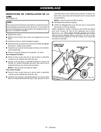
22 − Español ARMADO PARA REVISAR LA INSTALACIÓN DE LA HOJA DE LA SIERRA Vea la figura 19. AVISO: Para funcionar correctamente, los dientes de la hoja deben apuntar hacia la parte frontal de la sierra, hacia abajo. La inobservancia de esta advertencia podría causar daños a la hoja de la sierra, la si...
Page 119 - PARA INSTALAR EL PROTECCIÓN DE LA HOJA
23 − Español ARMADO PARA INSTALAR EL PROTECCIÓN DE LA HOJA Vea las figuras 20 y 21. ADVERTENCIA: Instale siempre la protección de la hoja y las garras que no permiten el retroceso en la cuchilla separadora en la posición “ascendente” para suministrar una cobertura de hoja adecuada. Instalar los comp...
Page 121 - PARA MOVAR LA SIERRA; ALMACENAMIENTO DE ACCESORIOS DE LA
25 − Español ARMADO PARA MOVAR LA SIERRA Vea la figura 24. Cierre el pedestal con patas como se describió en el Para abrir y cerrar (preparar y desmontar) el pedestal anteriormente en esta sección. Sosteniendo la plataforma con patas con firmeza, tire de ella hacia usted hasta que esta y la sier...
Page 122 - FUNCIONAMIENTO; APLICACIONES
26 − Español CAUSAS DE LOS CONTRAGOLPES El contragolpe puede ocurrir cuando la hoja se atasca o dobla, lanzando la pieza de trabajo hacia atrás, hacia usted, con gran fuerza y velocidad. Si tiene las manos cerca de la hoja de la sierra, pueden soltarse de la pieza de trabajo y tocar la hoja. Obviame...
Page 123 - AYUDAS PARA CORTAR
27 − Español FUNCIONAMIENTO Limpie el sierra, protección de la hoja, bajo el placa de la garanta, y bajo cualquier área donde sierra o pieza de trabajo o aserrín puede reunir Mantenga la protección de la hoja, la cuchilla separadora y los trinquetes anticontragolpe en su lugar y en un estado de ...
Page 124 - SOPORTES DE LA PIEZA DE TRABAJO
28 − Español FUNCIONAMIENTO SOPORTES DE LA PIEZA DE TRABAJO Vea la figura 31. Cuando corte con la sierra de mesa, asegúrese de que la pieza de trabajo esté bien sujetada. El soporte adecuado de la pieza de trabajo durante el proceso de corte no solo mejora la precisión del corte, sino que también pe...
Page 125 - PEINES DE SUJECIÓN; FORMA DE MONTAR UN PEINE DE SUJECIÓN
29 − Español FUNCIONAMIENTO Para utilizar vaivén: Posicione el pieza de trabajo plano sobre la mesa con el rubor de orilla contra la vaivén y contra la tope. Tener el mango de vaivén y utilizar un palos empujadora y/o bloque empujador, consulte Cómo efectuar cortes al hilo más adelante en esta s...
Page 126 - TIPOS DE CORTES
30 − Español FUNCIONAMIENTO CORTE AL HILO EN BISEL CORTE AL HILO CORTE TRANSVERSAL CORTE A INGLETE CORTE A INGLETE COMBINADO (CON BISEL) CORTE TRANSVERSAL EN BISEL 1 TIPOS DE CORTES Vea la figura 36. Existen seis cortes básicos: 1) el corte transversal, 2) el corte al hilo, 3) el corte a inglete, 4)...
Page 127 - PARA CAMBIAR LA PROFUNDIDAD DE LA; PARA AJUSTAR EL INDICADOR DE BISEL
31 − Español INDICADOR DE BISEL TORNILLO PALANCA DE FIJACIÓN DE BISEL GARGANTA FUNCIONAMIENTO PARA CAMBIAR LA PROFUNDIDAD DE LA HOJA Vea las figuras 37 y 38. Se debe ajustar la profundidad de la hoja de la sierra de manera que las puntas exteriores de la hoja queden más elevadas que la pieza de trab...
Page 128 - PARA USAR LA GUÍA DE CORTE AL HILO
32 − Español MARCA DE 51 mm (2 pulg.) FUNCIONAMIENTO PARA USAR LA GUÍA DE CORTE AL HILO Vea las figuras 40 y 41. ADVERTENCIA: Para reducir el riesgo de sufrir lesiones, siempre asegúrese de que la guía de corte al hilo esté paralela a la hoja, antes de iniciar cualquier operación. NOTA: La guía de c...
Page 129 - PARA USAR LAS EXTENSION DESLIZABLES
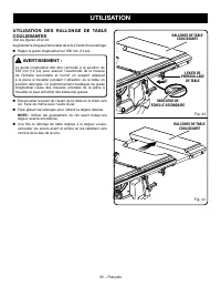
33 − Español PALANCA DE FIJACIÓN DE LA MESA EXTENSIÓN DE LA MESA DESLIZABLE EXTENSIÓN DE LA MESA DESLIZABLE FUNCIONAMIENTO PARA USAR LAS EXTENSION DESLIZABLES DE LA MESA Vea las figuras 43 y 44. Aumente la longitud de la mesa de la sierra usando la extensión de la mesa. Coloque la guía de corte al...
Page 130 - PARA USAR LA GUIA DE INGLETES
34 − Español Fig. 45 Fig. 46 FUNCIONAMIENTO PARA USAR LA GUIA DE INGLETES Vea la figura 45. La guía de ingletes brinda una gran precisión en los cortes en ángulo. Para efectuar cortes con tolerancias muy estrechas se recomienda efectuar cortes de prueba.El calibrador de ingletes puede girarse 60° a ...
Page 131 - FORMA DE EFECTUAR CORTES
35 − Español FUNCIONAMIENTO Si ambas distancias medidas son diferentes: Retirar la protección de la hoja, el cuchilla separadora y trinquetes anti contragolpe. Eleve lo más posible la hoja con un giro de la volante de ajuste de altura y bisel. Afloje los pernos de seguridad girándolos hacia la i...
Page 132 - PARA EFECTUAR CORTES TRANSVERSALES
36 − Español FUNCIONAMIENTO Fig. 50 CORTE TRANSVERSAL Fig. 49 Coloque siempre la pieza de trabajo contra la cara del cuerpo del medidor de inglete al realizar cortes. Para evitar que la pieza de trabajo se mueva, puede colocar un pedazo de papel de lija en la cara del cuerpo del medidor de inglete. ...
Page 133 - CÓMO EFECTUAR CORTES AL HILO
37 − Español Para realizar cortes transversales repetitivos, siga estos pasos: Se puede usar un bloque de detención como indicador de corte para realizar cortes transversales repetitivos de la misma longitud sin tener que marcar la pieza de trabajo para hacer cada corte. El extremo del bloque de det...
Page 135 - CÓMO EFECTUAR CORTES A INGLETE
39 − Español CÓMO EFECTUAR CORTES A INGLETE Vea la figura 54. ADVERTENCIA: Asegúrese de que esté instalado y funcione adecuadamente el conjunto de protección de la hoja para evitar posibles lesiones graves. Desmonte la guía de corte al hilo. Ajuste la hoja a la profundidad correcta para la pieza...
Page 136 - CÓMO EFECTUAR CORTES AL HILO EN BISEL
40 − Español GUÍA DE CORTE AL HILO CÓMO EFECTUAR CORTES AL HILO EN BISEL Vea la figura 57. ADVERTENCIA: Asegúrese de que esté instalado y funcione adecuadamente el conjunto de protección de la hoja para evitar lesiones graves. ADVERTENCIA: La guía de corte al hilo debe estar del lado derecho de la h...
Page 137 - COLOQUE LA MANO
41 − Español FUNCIONAMIENTO COLOQUE LA MANO IZQUIERDA LA GUÍA DE INGLETES AQUÍ C Ó M O E F E C T U A R C O RT E S A I N G L E T E COMBINADOS (EN BISEL) Vea la figura 58. ADVERTENCIA: Asegúrese de que esté instalado y funcione adecuadamente el conjunto de protección de la hoja para evitar posibles le...
Page 138 - CÓMO CORTAR UN PANEL GRANDE
42 − Español CÓMO CORTAR UN PANEL GRANDE Vea la figura 59. Asegúrese de que la sierra esté debidamente asegurada a una superficie de trabajo para evitar cualquier volcamiento producido por un panel grande. ADVERTENCIA: Asegúrese de que esté instalado y funcione adecuadamente el conjunto de protecció...
Page 139 - CÓMO EFECTUAR UN CORTE SIN TRASPASO
43 − Español FUNCIONAMIENTO CÓMO EFECTUAR UN CORTE SIN TRASPASO Vea la figura 60. Pueden efectuarse cortes sin traspaso (hizo con un estándar 10 pulg. hoja) del espesor de la pieza de trabajo paralelos a la fibra de la madera (corte al hilo) o transversales a la fibra (corte transversal). El corte s...
Page 140 - CÓMO EFECTUAR CORTES DE RANURA
44 − Español FUNCIONAMIENTO CÓMO EFECTUAR CORTES DE RANURA Vea la figura 61. Para este procedimiento se requiere una placa de la garganta para corte de ranuras optativa (vea la sección Accesorios de este manual y consulte al personal de la tienda de menudeo de su preferencia). Todos las hojas y jueg...
Page 141 - AJUSTES; PARA REEMPLAZAR LA HOJA
45 − Español AJUSTES ADVERTENCIA: Antes de efectuar cualquier ajuste, asegúrese de que la herramienta esté desconectada del suministro de corriente y que el botón superior del interruptor no esté presionado. La falta de atención a esta advertencia podría causar lesiones corporales graves. Para evita...
Page 142 - ̊ TORNILLO
46 − Español AJUSTES Después de la instalación, ajuste el indicador de escala de corte al hilo para adaptarlo al ancho de corte y el grosor de la hoja. Consulte el apartado Para ajustar a la hoja el indicador de la escala de la guía de corte al hilo en la sección Funcionamiento de este manual. En la...
Page 144 - MANTENIMIENTO GENERAL; MANTENIMIENTO; LUBRICACIÓN; PALANCA PARA
48 − Español ADVERTENCIA: Al dar servicio a la unidad, sólo utilice piezas de repuesto idénticas. El empleo de piezas diferentes puede causar un peligro o dañar el producto. ADVERTENCIA: Siempre póngase protección ocular con la marca de cumplimiento de la norma ANSI Z87.1. Si la operación genera muc...
Page 145 - VERTEDERO DE ASERRÍN; ACCESORIOS; PROBLEMA; TORNILLO
49 − Español MAINTENANCE VERTEDERO DE ASERRÍN Vea la figura 70. Esta sierra incluye un vertedero de aserrín práctico para descargar el aserrín. Puede conectar una aspiradora común al vertedero de aserrín, ubicado debajo de la parte trasera de la sierra.Durante períodos de uso prolongado, el verteder...
Page 146 - CORRECCIÓN DE PROBLEMAS
50 − Español CORRECCIÓN DE PROBLEMAS PROBLEMA CAUSA SOLUCIÓN El corte quema o aglutina la pieza de trabajo. La hoja no está afilada.La hoja se inclina. El trabajo es alimentado demasiado rápido.La guía de corte al hilo está desalineada.La pieza de trabajo está combada. Está desalineado el cuchilla s...