Page 3 - gENERAL SAFETy RULES; READ ALL iNSTRUCTiONS
3 gENERAL SAFETy RULES wARNiNg: Read and understand all instructions. Failure to follow all instructions listed below, may result in electric shock, fire and/or serious personal injury. READ ALL iNSTRUCTiONS KNOw yOUR POwER TOOL. Read the operator’s manual carefully. Learn the applications and lim...
Page 5 - SPECiFiC SAFETy RULES
5 KEEP hANDS AwAy FROM CUTTiNg AREA. Do not reach underneath work or in blade cutting path with hands and fingers for any reason. Always turn the power off. ALwAyS SUPPORT LONg wORKPiECES while cutting to minimize risk of blade pinching and kickback. Saw may slip, walk or slide while cutting lon...
Page 6 - SyMBOLS
6 SyMBOLS Some of the following symbols may be used on this tool. Please study them and learn their meaning. Proper interpretation of these symbols will allow you to operate the tool better and safer. Read Operator’s Manual Safety Alert No Hands Symbol SyMBOL NAME DESigNATiON/EXPLANATiON Voltage Cur...
Page 7 - ELECTRiCAL; EXTENSiON CORDS; DOUBLE iNSULATiON
7 ELECTRiCAL EXTENSiON CORDS When using a power tool at a considerable distance from a power source, be sure to use an extension cord that has the capacity to handle the current the tool will draw. An undersized cord will cause a drop in line voltage, resulting in overheating and loss of power. Use ...
Page 8 - gLOSSARy OF TERMS
8 gLOSSARy OF TERMS Push Blocks (jointer planers)Device used to feed the workpiece over the jointer planer cutterhead during any operation. This aid helps keep the operator’s hands well away from the cutterhead.Push Blocks (flooring and table saws)Device used to hold the workpiece during cutting ope...
Page 9 - FEATURES; KNOw yOUR FLOORiNg SAw; PRODUCT SPECiFiCATiONS
9 FEATURES KNOw yOUR FLOORiNg SAw See Figure 1, page 17. The safe use of this product requires an understanding of the information on the tool and in this operator’s manual as well as a knowledge of the project you are attempting. Before use of this product, familiarize yourself with all operating f...
Page 10 - ASSEMBLy; LOOSE PARTS LiST
10 ASSEMBLy LOOSE PARTS LiST See Figure 2, page 17. The following items are included with the saw: Key No. Description Qty. A Saw Handle .........................................................1 B Screws .................................................................2 C Blade Wrench ................
Page 11 - TO iNSTALL ThE FEET TO ThE SAw BASE; TO iNSTALL FENCE FOR MAKiNg RiP CUTS; TO USE ThE DUST BAg
11 ASSEMBLy TO iNSTALL ThE FEET TO ThE SAw BASE See Figure 6, page 18. Align hole in foot with hole in saw base. Insert a Phillips screw in the bottom of the foot and into the base. Tighten securely. Repeat for the other three feet. TO iNSTALL wORK CLAMP See Figure 7, page 19. wARNiNg: In some...
Page 12 - TO iNSTALL / REPLACE ThE BLADE; TO STORE ACCESSORiES; TO MOVE ThE SAw
12 ASSEMBLy TO iNSTALL / REPLACE ThE BLADE See Figures 11 - 12, pages 19 - 20. wARNiNg: A 5 in. blade is the maximum blade capacity of the saw. Never use a blade that is too thick. Larger blades will come in contact with the blade guard, while thicker blades will prevent the blade bolt from securing...
Page 13 - OPERATiON; APPLiCATiONS
13 OPERATiON wARNiNg: Do not allow familiarity with tools to make you care-less. Remember that a careless fraction of a second is sufficient to inflict serious injury. wARNiNg: Always wear eye protection with side shields marked to comply with ANSI Z87.1. Failure to do so could result in objects bei...
Page 14 - TO USE ThE iNDiCATOR; MAKiNg CUTS
14 OPERATiON wARNiNg: ALWAYS make sure your workpiece is not in contact with the blade before operating the switch to start the tool. Failure to heed this warning may cause the workpiece to be kicked back toward the operator and result in serious personal injury. wARNiNg: To reduce the risk of accid...
Page 15 - TO MAKE A CROSS CUT
15 OPERATiON wARNiNg: Always keep hands and body out of the path of the saw blade. Failure to heed this warning could result in per-sonal injury. TO MAKE A CROSS CUT See Figure 19, page 22. A cross cut is made by cutting across the width of the workpiece. Install the work clamp on the fence. Pla...
Page 16 - MAiNTENANCE; gENERAL MAiNTENANCE; ACCESSORiES
16 MAiNTENANCE wARNiNg: When servicing, use only identical replacement parts. Use of any other parts may create a hazard or cause product damage. wARNiNg: Always wear eye protection with side shields marked to comply with ANSI Z87.1 during product operation. If operation is dusty, also wear a dust m...
Page 17 - GARANTIE
2 Introduction ..................................................................................................................................................................... 2 Garantie ...........................................................................................................
Page 18 - RÈGLES DE SÉCURITÉ GÉNÉRALES; LIRE TOUTES LES INSTRUCTIONS
3 RÈGLES DE SÉCURITÉ GÉNÉRALES AVERTISSEMENT : Lire et veiller à bien comprendre toutes les instructions. Le non respect de toutes les instructions ci-dessous peut entraîner un choc électrique, un incendie et / ou des blessures graves. LIRE TOUTES LES INSTRUCTIONS V E I L L E R À B I E N C O N N A...
Page 20 - RÈGLES DE SÉCURITÉ PARTICULIÈRES
5 GARDER LES MAINS À L’ÉCART DE LA ZONE DE COUPE. Ne placer en aucun cas la main ou les doigts au-dessous de la pièce à couper ou sur la trajectoire de la lame. Toujours éteindre la scie. TOUJOURS SOUTENIR LES PIÈCES LONGUES pendant le travail, afin d’éviter les risques de pincement de la lame e...
Page 21 - SYMBOLES; SYMBOLE
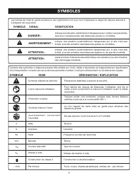
6 SYMBOLES Certains des symboles ci-dessous peuvent être utilisés sur l’outil. Veiller à les étudier et à apprendre leur signification. Une interprétation correcte de ces symboles permettra d’utiliser l’outil plus efficacement et de réduire les risques. Lire le manuel d’utilisation Symbole d’alerte ...
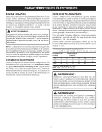
Page 22 - CARACTÉRISTIQUES ÉLECTRIQUES; CORDONS PROLONGATEURS; DOUBLE ISOLATION
7 CARACTÉRISTIQUES ÉLECTRIQUES CORDONS PROLONGATEURS Lors de l’utilisation d’un outil électrique à grande distance d’une prise secteur, veiller à utiliser un cordon prolongateur d’une capacité suffisante pour supporter l’appel de courant de l’outil. Un cordon de capacité insuffisante causerait une b...
Page 23 - GLOSSAIRE
8 GLOSSAIRE Trou pilote (perceuses à colonne)Petit trou pratiqué dans une pièce servant de guide pour assurer la précision d’un trou de plus grand diamètre.Blocs poussoirs (pour dégauchisseuses/raboteuses)Dispositif utilisés pour pousser le matériau contre la tête de coupe lors de toute opération. C...
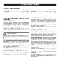
Page 24 - CARACTÉRISTIQUES; PRODUCT SPECIfICATIONS
9 CARACTÉRISTIQUES POUR SE fAMILIARISER AVEC LA SCIE À PLANCHER Voir la figure 1, page 17. L’utilisation sûre de ce produit exige une compréhension des renseignements figurant sur l’outil et contenus dans le manuel d’utilisation, ainsi qu’une bonne connaissance du projet entrepris. Avant d’utiliser ...
Page 25 - ASSEMBLAGE; LISTE DES PIÈCES DÉTACHÉE; DÉBALLAGE
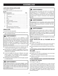
10 ASSEMBLAGE LISTE DES PIÈCES DÉTACHÉE Voir la figure 2, page 17. Les articles suivants sont inclus avec le scie : No. de Pièce Description Qté. A Poignée de la scie ...............................................1 b Vis ........................................................................2 C Cl...
Page 26 - POUR UTILISER DU SAC À POUSSIÈRE
11 ASSEMBLAGE POUR INSTALLER LE PIEDS À LA BASE DE LA SCIE Voir la figure 6, page 18. Aligner le trou dans le pied avec le trou dans la base de la scie. Insérer une vis Phillips dans le bas du pied et dans la base. Serrer fermement. Repita pour l’autre tres pieds. POUR INSTALLER DU BRIDE DE SE...
Page 27 - INSTALLATION / REMPLACEMENT DE LA LAME; POUR METTRE DES ACCESSOIRES; POUR DÉPLACER DE SCIE
12 INSTALLATION / REMPLACEMENT DE LA LAME Voir les figures 11 - 12, pages 19 - 20. AVERTISSEMENT : La taille maximum de lame pouvant être utilisée sur cette scie est de 5 po. Ne jamais utiliser une lame trop épaisse. Des lames de plus grandes dimensions toucheraient les protection de lame et des lam...
Page 28 - UTILISATION; APPLICATIONS; POUR ÉVITER LE REBOND; CONSEILS DE COUPE; POUR INTERRUPTEUR MARCHE / ARRÊT
13 UTILISATION AVERTISSEMENT : Ne pas laisser la familiarité avec l’outil faire oublier la prudence. Ne pas oublier qu’une fraction de seconde d’inattention peut entraîner des blessures graves. AVERTISSEMENT : Toujours porter une protection oculaire certifiée conforme à la norme ANSI Z87.1. Si cette...
Page 29 - POUR UTILISER L’INDICATEUR; EXÉCUTION DE COUPES
14 UTILISATION AVERTISSEMENT : TOUJOURS s’assurer que la pièce n’est pas en contact avec la lame avant de mettre le commutateur de l’outil en position de marche. Ne pas prendre cette précaution peut causer le rebond de la pièce en direction de l’opérateur et d’entraîner des blessures graves. AVERTIS...
Page 30 - POUR COUPES TRANSVERSALES
15 UTILISATION AVERTISSEMENT : Toujours garder les mains et le corps hors du passage de la lame. Ne pas prendre cette précaution pourrait entraîner des blessures graves. POUR COUPES TRANSVERSALES Voir la figure 19, page 22. La coupe est effectuée en travers du grain de la pièce de bois. Installer ...
Page 31 - ENTRETIEN; ENTRETIEN GÉNÉRAL; ACCESSOIRES
16 ENTRETIEN AVERTISSEMENT : Utiliser exclusivement des pièces d’origine pour les réparations. L’usage de toute autre pièce pourrait créer une situation dangereuse ou endommager l’outil. AVERTISSEMENT : Toujours porter une protection oculaire certifiée conforme à la norme ANSI Z87.1 lors de l’utilis...
Page 32 - GARANTÍA
2 Introducción ..................................................................................................................................................................... 2 Garantía ...........................................................................................................
Page 33 - REGLAS DE SEGURIDAD GENERALES; LEA TODAS LAS INSTRUCCIONES
3 REGLAS DE SEGURIDAD GENERALES ADVERTENCIA: Lea y comprenda todas las inst rucciones. El incumplimiento de las instrucciones señaladas abajo puede causar descargas eléctricas, incendios y lesiones serias. LEA TODAS LAS INSTRUCCIONES FAMILIARÍCESE CON SU HERRAMIENTA ELÉCTRICA. Lea cuidadosamente e...
Page 35 - REGLAS DE SEGURIDAD ESPECÍFICAS
5 MANTENGA LAS MANOS ALEJADAS DEL ÁREA DE CORTE. No trate de alcanzar bajo la pieza de trabajo o en la trayectoria de corte de la hoja con las manos y dedos por ninguna razón. Siempre apague la corriente. SIEMPRE APOYE LAS PIEZAS DE TRABAJO LARGAS mientras corta para reducir al mínimo el riesgo ...
Page 36 - SÍMBOLOS; SÍMBOLO SEÑAL
6 SÍMBOLOS Es posible que se empleen en esta herramienta algunos de los siguientes símbolos. Le suplicamos estudiarlos y aprender su significado. Una correcta interpretación de estos símbolos le permitirá utilizar mejor y de manera más segura la herramienta. SÍMBOLO NOMBRE DENOMINACIÓN/EXPLICACIÓN N...
Page 37 - ASPECTOS ELÉCTRICOS; DOBLE AISLAMIENTO; CORDONES DE EXTENSIÓN
7 ASPECTOS ELÉCTRICOS DOBLE AISLAMIENTO El doble aislamiento es una característica de seguridad de las herramientas eléctricas, la cual elimina la necesidad de usar el típico cordón eléctrico de tres conductores con conexión a tierra. Todas las partes metálicas expuestas están aisladas de los compon...
Page 38 - GLOSARIO DE TÉRMINOS
8 GLOSARIO DE TÉRMINOS Bloques empujadores (para cepillos de juntas)Son dispositivos empleados para avanzar la pieza de trabajo por el cepillo de juntas durante cualquier operación. Este medio ayuda al operador a mantener las manos alejadas de la cabeza de corte.Bloques empujadores (para sierras cor...
Page 39 - CARACTERÍSTICAS; ESPECIFICACIONES DEL PRODUCTO
9 CARACTERÍSTICAS FA M I L I A R Í C E S E C O N L A S I E R R A PA R A PISOS Vea la figura 1, página 17. El uso seguro que este producto requiere la comprensión de la información impresa en la herramienta y en el manual del operador así como ciertos conocimientos sobre el proyecto a realizar. Antes...
Page 40 - ARMADO; LISTA DE PIEZAS SUELTAS; PARA INSTALAR DEL MANGO DE LA SIERRA
10 ARMADO LISTA DE PIEZAS SUELTAS Vea la figura 2, página 17. Los siguientes accesorios vienen incluidos con sierra: Núm. ref. Descripción Cant. A Mango de la sierra ...............................................1 B Tornillo .................................................................2 C Llave...
Page 41 - PARA INSTALAR LA PRENSA DE TRABAJO; PARA UTILIZAR EL SACO CAPTAPOLVO
11 ARMADO PARA INSTALAR LOS PIES A LA BASE DE LA SIERRA Vea la figura 6, página 18. Alinee el agujero en el pata con el agujero en la base de la sierra. Inserte un tornillo Phillips en la parte inferior de la pata y en la base. Apriete firemente. Repita para otro tres patas. PARA INSTALAR LA P...
Page 42 - PARA INSTALAR O REEMPLAZAR LA HOJA; PARA GUARDAR EL ACCESORIOS; PARA MOVER LA SIERRA
12 ARMADO PARA INSTALAR O REEMPLAZAR LA HOJA Vea las figuras 11 - 12, páginas 19 - 20. ADVERTENCIA: La sierra tiene capacidad para hojas hasta de un diámetro de 5 pulg. Nunca utilice una hoja tan gruesa. Las hojas más grandes tocan las proteccion de la hoja, y las más gruesas impiden asegurarlas con...
Page 43 - FUNCIONAMIENTO; APLICACIONES
13 FUNCIONAMIENTO ADVERTENCIA: No permita que su familarización con las herramientas lo vuelva descuidado. Tenga presente que un descuido de un instante es suficiente para causar una lesión grave. ADVERTENCIA: Siempre póngase protección ocular con la marca de cumplimiento de la norma ANSI Z87.1. Si ...
Page 44 - PARA UTILIZAR EL INDICADOR; FORMA DE EFECTUAR CORTES
14 FUNCIONAMIENTO ADVERTENCIA: Cuando no esté en uso la herramienta, SIEMPRE retire la llave del interruptor y guárdela en un lugar seguro. En caso de un apagón, ponga el interruptor en la posición de OFF (apagado) y retire la llave. De esta manera se evita un arranque por accidente de la herramient...
Page 45 - PARA REALIZAR CORTES TRANSVERSALES; PARA EFECTUAR CORTES A INGLETE
15 FUNCIONAMIENTO ADVERTENCIA: Siempre mantenga las manos y el cuerpo fuera de la trayectoria de la hoja. La inobservancia de esta adver-tencia puede causar lesiones serias. PARA REALIZAR CORTES TRANSVERSALES Vea la figura 19, página 22. Los cortes transversales se efectúan cortando a través de la a...
Page 46 - MANTENIMIENTO; MANTENIMIENTO GENERAL; ACCESORIOS
16 MANTENIMIENTO ADVERTENCIA: Al dar servicio a la unidad, sólo utilice piezas de repuesto idénticas. El empleo de piezas diferentes puede causar un peligro o dañar el producto. ADVERTENCIA: Siempre póngase protección ocular con la marca de cumplimiento de la norma ANSI Z87.1. Si la operación genera...
Page 56 - PaRts and sERVicE; • HOw tO OBtAIN REpLAcEMENt pARtS:; PiÈcEs Et sERVicE
26 988000-0994-2 3 -10 (REV:02) OPERATOR’S MANUAL / MANUEL D’UTILISATION /MANUAL DEL OPERADOR 5 in. FLOORINg SAwSCIE À PLANChER DE 127 mm (5 po)SIERRA PARA PISOS DE 127 mm (5 pulg.) RLS1351 • PaRts and sERVicE Prior to requesting service or purchasing replacement parts, please obtain your model and ...


 Ryobi SS630
User Manual
Ryobi SS630
User Manual
 Ryobi 18A-C06-734
User Manual
Ryobi 18A-C06-734
User Manual
 Ryobi 21AB454B734
User Manual
Ryobi 21AB454B734
User Manual
 Ryobi 41CD875A034
User Manual
Ryobi 41CD875A034
User Manual
 Ryobi 767R
User Manual
Ryobi 767R
User Manual
 Ryobi 2079R
User Manual
Ryobi 2079R
User Manual
 Ryobi 725R
User Manual
Ryobi 725R
User Manual
 Ryobi 890R
User Manual
Ryobi 890R
User Manual
 Ryobi 825R
User Manual
Ryobi 825R
User Manual
 Ryobi 96116000202
User Manual
Ryobi 96116000202
User Manual