Page 2 - TABLE OF CONTENTS; TABLE DES MATIÈRES / ÍNDICE DE CONTENIDO; INTRODUCTION; INTRODUCTION / INTRODUCCIóN
Page 2 Introduction ....................................................................................................................................... 2 Introduction / Introducción Important Safety Instructions .................................................................................
Page 3 - Read and understand all instructions.; READ ALL INSTRUCTIONS; DANGER —; IMPORTANT SAFETY INSTRUCTIONS
Page 3 — English WARNING: Read and understand all instructions. Failure to follow all instructions listed below may result in electric shock, fire, and/or serious personal injury. READ ALL INSTRUCTIONS For safe operation, read and understand all in- structions before using this product. Be familia...
Page 4 - With a basic understanding of kickback, you; SPECIFIC SAFETY RULES
Page 4 — English Kickback is a dangerous reaction that can lead to serious injury. Kickback may occur when the moving chain contacts an object at the upper portion of the tip of the guide bar or when the wood closes in and pinches the chain in the cut. Contact at the upper portion of the tip of th...
Page 6 - SYMBOL; SYMBOLS
Page 6 — English Some of the following symbols may be used on this product. Please study them and learn their meaning. Proper interpretation of these symbols will allow you to operate the product better and safer. SYMBOL NAME EXPLANATION Safety Alert Symbol Indicates a potential personal injury haza...
Page 7 - NOTICE
Page 7 — English The following signal words and meanings are intended to explain the levels of risk associated with this product. SYMBOL SIGNAL MEANING DANGER: Indicates an imminently hazardous situation, which, if not avoided, will result in death or serious injury. WARNING: Indicates a potentially...
Page 8 - PRODUCT SPECIFICATIONS; FEATURES
Page 8 — English PRODUCT SPECIFICATIONS Motor ..................................................................................................................................... 18 Volt DCBar Length ......................................................................................................
Page 9 - KNOW YOUR POLE SAW; This product requires assembly.; PACKING LIST
Page 9 — English KNOW YOUR POLE SAW See Figure 1. The safe use of this product requires an under-standing of the information on the product and in this operator’s manual as well as a knowledge of the project you are attempting. Before use of this product, familiarize yourself with all operating feat...
Page 10 - CONNECTING THE POLES; Insert the plug on the intermediate pole into the; ASSEMBLY
Page 10 — English Fig. 2 WARNING: To prevent accidental starting that could cause serious personal injury, always remove the bat-tery pack from the product when assembling parts. CONNECTING THE POLES See Figure 2. Insert the plug on the intermediate pole into the socket on the handle pole and push...
Page 11 - ATTACHING THE SHOULDER; Connect the latches on the shoulder harness to; OPERATION; APPLICATIONS; Limbing; latch
Page 11 — English ASSEMBLY ATTACHING THE SHOULDER HARNESS See Figure 3. Connect the latches on the shoulder harness to the strap hangers. Adjust the strap to a comfortable position. Fig. 3 OPERATION DANGER: Never cut near power lines, electric cords, or other electric sources. If bar and chain j...
Page 12 - ADDING BAR AND CHAIN LUBRICANT; Pole saw comes from the factory with no; TO INSTALL / REMOVE BATTERY; To avoid serious personal injury, always
Page 12 — English CHAIN LUBRICANT Fig. 4 caP quick view oil indicator OPERATION Fig. 5 lock-out button switch trigger battery ADDING BAR AND CHAIN LUBRICANT See Figure 4. Use Bar and Chain Lubricant. It is designed for chains and chain oilers, and is formulated to perform over a wide temperature ran...
Page 13 - STARTING AND STOPPING; BASIC CUTTING PROCEDURE
Page 13 — English STARTING AND STOPPING See Figure 5 - 6. To start the motor: Hold the pole saw as shown and ensure that you are well away from anything that may contact the blade. Press and hold the trigger lock-out. Depress the switch trigger. To stop the motor: Release the trigger t...
Page 14 - LIMBING AND PRUNING
Page 14 — English Failure to follow proper cutting procedures will result in the bar and chain binding and becom-ing pinched or trapped in the limb. If this should happen: Stop the motor and remove the battery pack. If the limb can be reached from the ground, lift the limb while holding the saw....
Page 15 - GENERAL MAINTENANCE; Stop the motor and remove the battery pack; Replacing the Bar; for additional information.; Flats; MAINTENANCE
Page 15 — English WARNING: When servicing, use only identical replacement parts. Use of any other parts could create a hazard or cause product damage. WARNING: Always wear eye protection with side shields marked to comply with ANSI Z87.1, along with head protection. Failure to do so could result in ...
Page 16 - REPLACING THE BAR AND CHAIN
Page 16 — English NOTE: New chain tends to stretch; check chain tension frequently and tension as required. NOTICE: Chain tensioned while warm, can be too tight upon cooling. Check the “cold tension” before next use. REPLACING THE BAR AND CHAIN See Figures 13 - 16. WARNING: To avoid possible serious...
Page 17 - CHAIN OILER
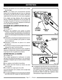
Page 17 — English CHAIN OILER See Figure 17. Use Premium Bar and Chain Lubricant. It is designed for chains and chain oilers and is formulated to perform over a wide temperature range with no dilution required. Remove the cap and carefully pour approxi- mately 2 oz. of bar and chain lubricant in...
Page 18 - HOW TO SHARPEN THE CUTTERS
Page 18 — English cutting corner side Plate dePth gauge toe gullet heel rivet hole toP Plate Parts oF a cutter Fig. 19 HOW TO SHARPEN THE CUTTERS See Figures 19 - 22. Be careful to file all cutters to the specified angles and to the same length, as fast cutting can be obtained only when all cutters ...
Page 19 - STORING THE PRODUCT; scabbard; PROBLEM; Chain Tension; call us First; For any questions about operating or maintaining your product,
Page 19 — English STORING THE PRODUCT See Figure 23. Clean all foreign material from the product. Store idle unit indoors in a dry, well-ventilated area that is inaccessible to children. Keep away from corrosive agents such as garden chemicals and de-icing salts. Always place the scabbard on t...
Page 20 - WARRANTY; LIMITED WARRANTY STATEMENT
Page 20 — English WARRANTY LIMITED WARRANTY STATEMENT Techtronic Industries North America, Inc., warrants to the original retail purchaser that this RYOBI ® brand outdoor product is free from defect in material and workmanship and agrees to repair or replace, at Techtronic Industries North America, ...
Page 21 - notes
Page 22 - LIRE TOUTES LES INSTRUCTIONS; DANGER —; INSTRUCTIONS IMPORTANTES CONCERNANT LA SÉCURITÉ
Page 3 — Français AVERTISSEMENT : Lire et veiller à bien comprendre toutes les instructions. Le non-respect des instructions ci-dessous peut entraîner une électrocution, un incendie et des blessures graves. LIRE TOUTES LES INSTRUCTIONS Pour travailler en toute sécurité, lire et veiller à bien comp...
Page 23 - Une compréhension élémentaire du rebond; RÈGLES DE SÉCURITÉ PARTICULIÈRES
Page 4 — Français Le rebond est une réaction dangereuse pouvant entraîner des blessures graves. Le rebond se produit lorsque la chaîne en rotation heurte un objet dans la partie supérieure de l’extrémité du guide ou lorsque l’entaille se referme et pince la chaîne dans le bois. Le contact de la pa...
Page 25 - SyMbOLE; SyMbOLES
Page 6 — Français Certains des symboles ci-dessous peuvent être utilisés sur le produit. Veiller à les étudier et apprendre leur signification pour assurer la sécurité d’utilisation. SyMbOLE NOM EXPLICATION Symbole d’alerte de sécurité Indique un risque de blessure potentiel. Lire le manuel d’utilis...
Page 26 - Indique une situation potentiellement dangereuse qui,; aVIS
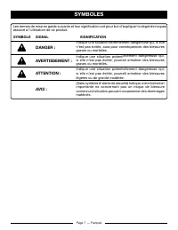
Page 7 — Français Les termes de mise en garde suivants et leur signification ont pour but d’expliquer le degré de risques associé à l’utilisation de ce produit. SyMbOLE SIGNAL SIGNIFICATION DANGER : Indique une situation extrêmement dangereuse qui, si elle n’est pas évitée, aura pour conséquences de...
Page 27 - FICHE TECHNIQUE; CARACTÉRISTIQUES
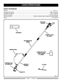
Page 8 — Français FICHE TECHNIQUE Moteur ...................................................................................................................................... 18 V c.c.Longueur du guide ....................................................................................................
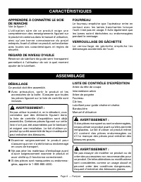
Page 28 - Ce produit doit être assemblé.; Ne pas utiliser le produit si, en le déballant, vous; Examiner soigneusement le produit pour
Page 9 — Français LISTE DE CONTRÔLE D’EXPÉDITION Arbre du tête de coupeIntermédiaire arbreArbre de poignèeFourreauClé hex.Lubrifiant pour guide-chaîne et chaîneBandoulièreManuel d’utilisation AVERTISSEMENT : Si des pièces manquent ou sont endommagées, ne pas utiliser ce produit avant qu’elles aient ...
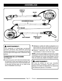
Page 29 - CONNEXION DU LE POIGNÈE; Insérer le bouchon de l’arbre intermédiaire dans; ASSEMbLAGE
Page 10 — Français AVERTISSEMENT : Pour empêcher un démarrage accidentel pouvant entraîner des blessures graves, toujours déconnecter le fil de bougie de moteur de la bougie d’allumage avant d’assembler des pièces. CONNEXION DU LE POIGNÈE Voir la figure 2. Insérer le bouchon de l’arbre intermédiai...
Page 30 - INSTALLATION DE LA bANDOULIÈRE; Fixer les crochets de la bandoulière aux fixations; UTILISATION; de réparations agréé pour obtenir de l’aide.; crochet
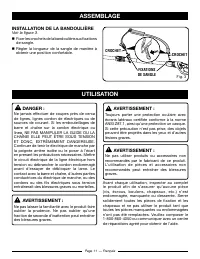
Page 11 — Français ASSEMbLAGE INSTALLATION DE LA bANDOULIÈRE Voir la figure 3. Fixer les crochets de la bandoulière aux fixations de sangle. Régler la longueur de la sangle de manière à obtenir une position confortable. UTILISATION DANGER : Ne jamais effectuer de coupes près de cerca de lignes, ...
Page 31 - être vérifiée à tous les 20 minutes d’utilisation et; PILES
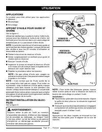
Page 12 — Français Fig. 4 Bouchon regard de niVeau d’huile APPLICATIONS Ce produit peut être utilisé pour les application ci-dessous : Ébranchage Émondage APPOINT D’HUILE POUR GUIDE ET CHAÎNE Voir la figure 4. Utiliser de lubrifant pour guide et chaîne. Cette huile, conçue pour les chaînes et hu...
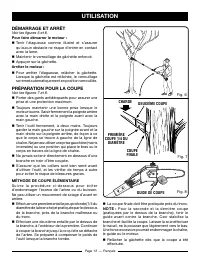
Page 32 - DÉMARRAGE ET ARRÊT; Voir les figures 5 et 6.; Pour faire démarrer le moteur :; PRÉPARATION POUR LA COUPE; Voir les figures 7 et 8.; MÉTHODE DE COUPE ÉLÉMENTAIRE; effectuer une première entaille peu profonde (1/4 du
Page 13 — Français DÉMARRAGE ET ARRÊT Voir les figures 5 et 6. Pour faire démarrer le moteur : Tenir l’élagueuse comme illustré et s’assurer qu’aucun obstacle ne risque d’entrer en contact avec la lame. Maintenir le verrouillage de gâchette enfoncé. Appuyer sur la gâchette. Arrêter le moteur :...
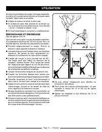
Page 33 - ÉbRANCHAGE ET ÉMONDAGE; Voir les figures 9 et 10.
Page 14 — Français Si la bonne procédure de coupe n’est pas respectée, la chaîne et le guide seront pincés ou bloqués dans l’entaille. Dans cette éventualité : Arrêtez le moteur et retirer le bloc-pile. Si la branche peut être atteinte en se tenant au sol, la soulever tout en tenant la scie. Cec...
Page 34 - ENTRETIEN GÉNÉRAL; Couper le moteur et retirer le bloc-pile avant; Remplacement du guide et de; plus loin dans ce manuel, pour des; ENTRETIEN; méplats
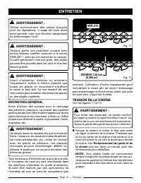
Page 15 — Français AVERTISSEMENT : Utiliser exclusivement des pièces d’origine pour les réparations. L’usage de toute autre pièce pourrait créer une situation dangereuse ou endommager l’outil. AVERTISSEMENT : Toujours porter une protection oculaire avec écrans latéraux certifiée conforme à la norme ...
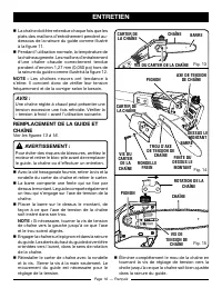
Page 36 - /4 de tour vers la gauche. Resserrer fermement; ENTRETIEN DE LA CHAÎNE
Page 17 — Français Serrer fermement la vis du carter de la chaîne de montage. NOTE : La chaîne est correctement tendue lorsqu’elle ne présente pas de mou en dessous du guide et qu’elle est bien serrée mais peut cependant être tournée à la main sans se gripper. Si la chaîne est trop tendue, elle ne...
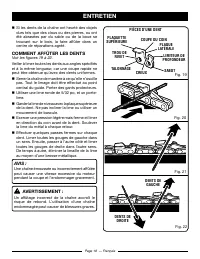
Page 37 - COMMENT AFFûTER LES DENTS
Page 18 — Français Si les dents de la chaîne ont heurté des objets durs tels que des clous ou des pierres, ou ont été abrasées par du sable ou de la boue se trouvant sur le bois, la faire affûter dans un centre de réparations agréé. COMMENT AFFûTER LES DENTS Voir les figures 19 à 22. Veiller à lim...
Page 38 - REMISAGE LE PRODUIT; fourreau; PRObLÈME; Tension de la chaîne; nous appeler d’aBord; BESOIN D’AID
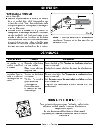
Page 19 — Français REMISAGE LE PRODUIT Voir la figure 23. Nettoyer soigneusement le produit. La remiser dans un endroit bien aéré, inaccessible aux enfants. La tenir à l’écart de produits corrosifs, tels que les produits chimiques de jardinage et le sel de dégivrage. Toujours placer le fourrea...
Page 39 - GARANTIE; ÉNONCÉ DE LA GARANTIE LIMITÉE
Page 20 — Français GARANTIE ÉNONCÉ DE LA GARANTIE LIMITÉE Techtronic Industries North America, Inc., garantit à l’acheteur original que ce produit RYoBI ® est exempt de tous vices de matériaux ou de fabrication et s’engage à réparer ou remplacer gratuitement, à son choix, tout produit s’avérant défe...
Page 41 - Lea y comprenda todas las instrucciones.; LEA ToDAs LAs INsTRuCCIoNEs; pELIgRo —; INsTRuCCIoNEs DE sEguRIDAD IMpoRTANTEs
Página 3 — Español ADVERTENCIA: Lea y comprenda todas las instrucciones. El incumplimiento de las instrucciones señaladas abajo puede causar descargas eléctricas, incendios y lesiones corporales serias. LEA ToDAs LAs INsTRuCCIoNEs Para la operación segura, lea y entienda todas las instrucciones an...
Page 42 - Con un conocimiento básico del contragolpe; REgLAs DE sEguRIDAD EspECÍFICAs
Página 4 — Español El contragolpe es una reacción peligrosa de la herramienta que puede ocasionar lesiones serias. El contragolpe ocurre cuando la cadena en movimiento hace contacto con un objeto en la parte superior de la punta de la barra, o cuando la madera se cierra y pellizca la cadena en el ...
Page 44 - REGLAS DE SEGURIDAD ESPECÍFICAS
Página 5 — Español Para evitar un arranque accidental; nunca traslade la unidad con la paquete de baterias instalado o el dedo en el gatillo del interruptor. Dé mantenimiento con cuidado a le producto — Mantenga afilado el filo de corte y límpielo para lograr un desempeño óptimo de la unidad y p...
Page 45 - sÍMboLo sEÑAL; aviso; sÍMboLos
Página 7 — Español Las siguientes palabras de señalización y sus significados tienen el objeto de explicar los niveles de riesgo relacionados con este producto. sÍMboLo sEÑAL sIgNIFICADo pELIgRo: Indica una situación peligrosa inminente, la cual, si no se evita, causará la muerte o lesiones serias. ...
Page 46 - EspECIFICACIoNEs DEL pRoDuCTo; CARACTERÍsTICAs
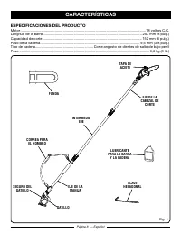
Página 8 — Español EspECIFICACIoNEs DEL pRoDuCTo Motor ............................................................................................................................... 18 voltios C.C.Longitud de la barra ....................................................................................
Page 47 - Este producto requiere armarse.
Página 9 — Español FAMILIARÍCEsE CoN su sIERRA DE péRTIgA Vea la figura 1. Para usar este producto con la debida seguridad se debe comprender la información indicada en la producto misma y en este manual, y se debe comprender también el trabajo que intenta realizar. Antes de usar este producto, fami...
Page 48 - CÓMo ACopLAR EL MANgo; Inserte el enchufe de la barra intermedia en el; ARMADo
Página 10 — Español ADVERTENCIA: No intente modificar este producto ni hacer accesorios no recomendados para la misma. Cualquier alteración o modificación constituye maltrato el cual puede causar una condición peligrosa, y como consecuencia posibles lesiones corporales serias. ADVERTENCIA: Para evit...
Page 49 - MoNTAJE DE LA CoRREA pARA EL; Enganche los broches del arnés para los; FuNCIoNAMIENTo; n eléctrico o de otras fuentes eléctricas.; bRochE
Página 11 — Español ARMADo MoNTAJE DE LA CoRREA pARA EL HoMbRo Vea la figura 3. Enganche los broches del arnés para los hombros en las asas para correas. Ajuste la correa para dejarla en una posición cómoda. FuNCIoNAMIENTo pELIgRo: Nunca couper cerca de líneas de corriente, cord ó n eléctrico o ...
Page 50 - ApLICACIoNEs
Página 12 — Español Fig. 4 tapa inDicaDoR DE niVEl DE acEitE ApLICACIoNEs Este producto puede emplearse para los fines enumerado abajo: Desramado Poda AbAsTECIMIENTo DE LubRICANTE pARA LA bARRA y LA CADENA Vea la figura 4. Use lubricante para barra y cadena. Está diseñado para las cadenas y los ...
Page 51 - ARRANQuE y ApAgADo; Vea las figuras 5 y 6.; para arrancar el motor:; pREpARACIÓN pARA EL CoRTE; Vea las figuras 7 y 8.; Procedimiento básico de corte; coRtE final
Página 13 — Español ARRANQuE y ApAgADo Vea las figuras 5 y 6. para arrancar el motor: Sujete la sierra de pértiga como se muestra y asegúrese de estar alejado de cualquier cosa que pueda tocar la hoja de corte. Oprima y no suelte el seguro del gatillo. Oprima el gatillo del interruptor. Apagar...
Page 52 - DEsRAMADo y poDA; Vea las figuras 9 y 10.
Página 14 — Español Suelte el gatillo tan pronto como se termine el corte. Si no se sigue el procedimiento correcto de corte, la barra y la cadena se atoran y quedan pellizcadas o atrapadas en la rama. Si sucede esto: Apague el motor y retire el paquete de baterías. Si la rama se puede alcanza...
Page 53 - S i e m p re p ó n g a s e p ro t e c c i ó n o c u l a r c o n; La inobservancia de esta; MANTENIMIENTo gENERAL; Apague el motor y retire el paquete de baterías; Cómo reemplazar la barra; MANTENIMIENTo; paRtES planaS
Página 15 — Español ADVERTENCIA: Al dar servicio a la unidad, sólo utilice piezas de repuesto idénticas. El empleo de piezas diferentes puede causar un peligro o dañar el producto. ADVERTENCIA: S i e m p re p ó n g a s e p ro t e c c i ó n o c u l a r c o n protección lateral con la marca de cumplim...
Page 54 - REEMpLAZo LA bARRA y; CADENA
Página 16 — Español RanURa DEl poStE DE montajE oRificio DE la ESpiga tEnSoRa DE la caDEna RUEDa DEntaDa ESpiga tEnSoRa DE la caDEna toRnillo DE la tapa DE la caDEna aRanDEla DE SEgURiDaD poStE DE montajE tapa DE la caDEna baRRa La cadena debe volver a tensarse cada vez que las partes planas de lo...
Page 55 - LubRICADoR DE LA CADENA
Página 17 — Español Elimine toda la holgura de la cadena girando el tornillo tensor en el sentido de las manecillas del reloj, asegurándose que la cadena asienta dentro de la ranura de la barra durante el tensionado. Apriete firmemente la tornillo de la tapa de la cadena. NoTA: La cadena está te...
Page 56 - FoRMA DE AFILAR Los DIENTEs DE
Página 18 — Español El ajuste de la profundidad determina la profundidad a la que el diente de corte entra en la madera y el tamaño de la viruta de madera que se quita. Demasiado claro aumenta el peligro de contragolpe. Muy poco claro disminuye el tamaño de los pedazos de madera, disminuyendo la h...
Page 57 - ALMACENAMIENTo DE LA; fUnDa; pRobLEMA; Tensado de la; llámEnoS pRimERo; ¿NECESITA A
Página 19 — Español ALMACENAMIENTo DE LA pRoDuCTo Vea la figura 23. Limpie todo material extraño de la producto. Almacene la unidad en un espacio bien ventilado inaccesible a los niños. Evite que la unidad entre en contacto con agentes corrosivos como las sustancias químicas para el jardín y las s...
Page 58 - gARANTÍA; DECLARACIÓN DE LA gARANTÍA LIMITADA
Página 20 — Español gARANTÍA DECLARACIÓN DE LA gARANTÍA LIMITADA Techtronic Industries North America, Inc. garantiza al comprador original al menudeo que este producto de la marca RYOBI ® carece de defectos en los materiales y en la mano de obra, y acuerda reparar o remplazar, a la sola discreción d...
Page 59 - notAs
Page 60 - OPERATOR’S MANUAL / 18 VOLT POLE SAW; MANUEL D’UTILISATION /; MANUAL DEL OPERADOR /; TECHTRONIC INDUSTRIES NORTH AMERICA, INC.; CALIFORNIA PROPOSITION 65; CALIFORNIA - PROPUESTA DE
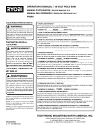
9900000684-11-12 (REV:01) OPERATOR’S MANUAL / 18 VOLT POLE SAW MANUEL D’UTILISATION / SCIE DE MANCHE 18 V MANUAL DEL OPERADOR / SIERRA DE PÉRTIGA DE 18 V P4360 TECHTRONIC INDUSTRIES NORTH AMERICA, INC. 1428 Pearman Dairy Road, Anderson, SC 29625 USA 1-800-860-4050 • www.ryobitools.com A subsidiary o...


 Ryobi SS630
User Manual
Ryobi SS630
User Manual
 Ryobi 18A-C06-734
User Manual
Ryobi 18A-C06-734
User Manual
 Ryobi 21AB454B734
User Manual
Ryobi 21AB454B734
User Manual
 Ryobi 41CD875A034
User Manual
Ryobi 41CD875A034
User Manual
 Ryobi 767R
User Manual
Ryobi 767R
User Manual
 Ryobi 2079R
User Manual
Ryobi 2079R
User Manual
 Ryobi 725R
User Manual
Ryobi 725R
User Manual
 Ryobi 890R
User Manual
Ryobi 890R
User Manual
 Ryobi 825R
User Manual
Ryobi 825R
User Manual
 Ryobi 96116000202
User Manual
Ryobi 96116000202
User Manual