Page 2 - TABLE OF CONTENTS
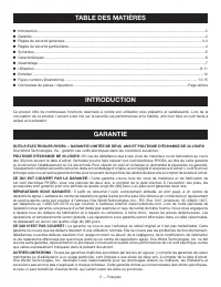
2 — English Introduction .......................................................................................................................................................................2 Warranty ................................................................................................
Page 3 - gENERAL SAFETY RULES; ELECTRICAL SAFETY
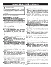
3 — English gENERAL SAFETY RULES WARNINg - Read all instructions. Failure to follow all instructions listed below may result in electric shock, fire and/or serious injury. The term “power tool” in all of the warnings listed below refers to your mains-operated (corded) power tool or battery-operated ...
Page 4 - SERvICE; BATTERY TOOL USE AND CARE
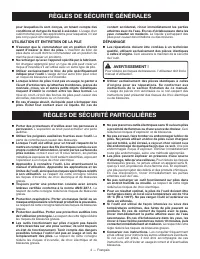
4 — English occurs, flush with water. If liquid contacts eyes, additionally seek medical help. Liquid ejected from the battery may cause irritation or burns. SERvICE Have your power tool serviced by a qualified repair person using only identical replacement parts. This will ensure that the safety ...
Page 5 - SYMBOLS
5 — English Some of the following symbols may be used on this product. Please study them and learn their meaning. Proper interpretation of these symbols will allow you to operate the product better and safer. SYMBOL NAME DESIgNATION/EXPLANATION Safety Alert Indicates a potential personal injury haza...
Page 6 - FEATURES
6 — English FEATURES PRODUCT SPECIFICATIONS Chuck .......................................................... 1/2 in. KeylessMotor ..................................................................18 Volt DCSwitch ..........................................................Variable SpeedNo Load Speed ....
Page 7 - ASSEMBLY; UNPACKINg; OPERATION
7 — English NOTE: Be sure hex hole for depth stop rod sits on top of collar. Slide depth stop rod into hex shaped hole on top of collar. Slide depth stop rod clamp into notch in collar. Clamp holds depth rod firmly in place. NOTE: When properly installed, the teeth on the depth stop rod should b...
Page 9 - DRILL MODE
9 — English WARNINg: Do not hold the chuck body with one hand and use the power of the drill to tighten the chuck jaws on the drill bit. The chuck body could slip in your hand, or your hand could slip and come in contact with the rotating drill bit. This could cause an accident resulting in serious ...
Page 11 - DRILLINg
11 — English METAL DRILLING For maximum performance, use high speed steel bits for metal or steel drilling. Select drilling mode. Begin drilling at a very low speed to prevent the bit from slipping off the starting point. Maintain a speed and pressure which allows cutting without overheating...
Page 12 - TO RETIgHTEN A LOOSE CHUCK; MAINTENANCE; CHUCK REMOvAL; FRENCH AND SPANISH LANgUAgE SECTIONS.; gENERAL MAINTENANCE
12 — English TO RETIgHTEN A LOOSE CHUCK The chuck may become loose on the spindle and develop a wobble. Also, the chuck screw may become loose, causing the chuck jaws to bind and prevent them from closing.To tighten: Remove the battery pack. Lock the switch trigger by placing the direction of ro...
Page 13 - TABLE DES MATIÈRES
2 — Français Introduction .......................................................................................................................................................................2 Garantie ...............................................................................................
Page 14 - RÈGLES DE SÉCURITÉ GÉNÉRALES; SÉCURITÉ ÉLECTRIQUE
3 — Français RÈGLES DE SÉCURITÉ GÉNÉRALES AVERTISSEMENT - Lire toutes les instructions. Le non-respect de toutes les instructions ci-dessous peut entraîner un choc électrique, un incendie et/ou des blessures graves. Le terme « outil motorisé », utilisé dans tous les avertissements ci-dessous désigne...
Page 15 - UTILISATION ET ENTRETIEN DE LA PILE
4 — Français RÈGLES DE SÉCURITÉ GÉNÉRALES RÈGLES DE SÉCURITÉ PARTICULIÈRES pour lesquelles ils sont conçus, en tenant compte des conditions et du type de travail à exécuter. L’usage d’un outil motorisé pour des applications pour lesquelles il n’est pas conçu peut être dangereux. UTILISATION ET ENTRE...
Page 16 - SYMBOLES
5 — Français Certains des symboles ci-dessous peuvent être utilisés sur produit. Veiller à les étudier et à apprendre leur signification. Une interprétation correcte de ces symboles permettra d’utiliser produit plus efficacement et de réduire les risques. SYMBOLE NOM DÉSIGNATION / EXPLICATION Symbol...
Page 17 - CARACTÉRISTIQUES; SÉLECTEUR DE SENS DE ROTATION
6 — Français CARACTÉRISTIQUES FICHE TECHNIQUE Mandrin ........................................ 13mm (1/2 po), sans cléMoteur ...................................................................18 V c.c.Commutateur .............................................Vitesse variableVitesse à vide ..............
Page 18 - ASSEMBLAGE; DÉBALLAGE; UTILISATION
7 — Français NOTE : S’assurer que le trou hexagonal servant pour la tige de butée de profondeur est positionné sur le dessus du collier. Glisser la tige de butée de profondeur dans le trou hex- agonal situé sur le dessus du collier. Glisser la bride de la tige de butée de profondeur dans l’enc...
Page 19 - APPLICATIONS; INSTALLATION DU BLOCS-PILES; VITESSE VARIABLE
8 — Français AVERTISSEMENT : Ne pas utiliser d’outils ou accessoires non recommandés par le fabricant pour cet outil. L’utilisation de pièces et accessoires non recommandés peut entraîner des blessures graves. APPLICATIONS Ce produit peut être utilisé pour les applications ci-dessous : Perçage de ...
Page 20 - VERROUILLAGE DE BROCHE INTERNE; TRAIN D’ENGRENAGES À DEUX VITESSES; SÉLECTEUR DE MODE RAPIDE; MODE DE PERÇAGE
9 — Français VERROUILLAGE DE BROCHE INTERNE Le verrouillage de broche interne permet à l’utilisateur de contrôler d’une seule main les réglages du mandrin et les changements de foret. Serrer le corps du mandrin pour empêcher les mors de tourner. Pour changer les forets et régler le mandrins, serrer ...
Page 21 - MAGTRAYTM
10 — Français Pour régler la butée de profondeur : Verrouiller la gâchette en mettant le sélecteur de sens de rotation en position centrale. Desserrer la poignée auxiliaire en tournant le bouton vers la gauche. Ajuster la tige de butée de profondeur de façon à ce que le foret dépasse son extré...
Page 22 - PERÇAGE
11 — Français UTILISATION PERÇAGE Voir la figure 14, page 15. Vérifier la position du sélecteur de rotation (rotation avant ou arrière). bloquer la pièce de travail dans un étau ou avec des serre-joints, pour l’empêcher de tourner avec le foret. Tenir la perceuse fermement et placer la pointe ...
Page 23 - ENTRETIEN; RETRAIT DU MANDRIN; SERRAGE D’UN MANDRIN DESSERRÉ
12 — Français AVERTISSEMENT : Utiliser exclusivement des pièces Ryobi d’origine pour les réparations. L’usage de toute autre pièce pourrait créer une situation dangereuse ou endommager l’outil. AVERTISSEMENT : Toujours porter une protection oculaire avec écrans latéraux certifiée conforme à la norme...
Page 24 - ÍNDICE DE CONTENIDO
2 — Español Introducción .......................................................................................................................................................................2 Garantía ................................................................................................
Page 25 - REGLAS DE SEGURIDAD GENERALES; GUARDE ESTAS INSTRUCCIONES; EMPLEO Y CUIDADO DE LA HERRAMIENTA
3 — Español REGLAS DE SEGURIDAD GENERALES ADVERTENCIA - Lea todas las instrucciones. El incumplimiento de las instrucciones señaladas abajo puede causar descargas eléctricas, incendios y lesiones serias. El término “herramienta eléctrica” empleado en todos los avisos de advertencia enumerados abajo ...
Page 26 - SERVICIO
4 — Español REGLAS DE SEGURIDAD GENERALES REGLAS DE SEGURIDAD ESPECÍFICAS Utilice la herramienta eléctrica, los accesorios y brocas, hojas y cuchillas de corte, ruedas de esmeril, etc. de conformidad con estas instrucciones, y de la forma apropiada para cada una de dichas herramientas, tomando en ...
Page 27 - SÍMBOLOS
5 — Español Es posible que se empleen en este producto algunos de los siguientes símbolos. Le suplicamos estudiarlos y aprender su significado. Una correcta interpretación de estos símbolos le permitirá utilizar mejor y de manera más segura el producto. SÍMBOLO NOMBRE DENOMINACIÓN/EXPLICACIÓN Alerta...
Page 28 - CARACTERÍSTICAS; BaNdEja MagTRaYTM
6 — Español CARACTERÍSTICAS ESPECIFICACIONES DEL PRODUCTO Portabrocas .............13 mm (1/2 pulg.), de apriete sin llaveMotor .......................................................... 18 V, corr. cont.Interruptor .............................................. Velocidad variableVelocidad en vacío ...
Page 29 - ARMADO; DESEMPAQUETADO; FUNCIONAMIENTO
7 — Español Deslice el collar del mango por el tornillo y coloque el ex- tremo hexagonal del collar dentro del orificio hexagonal. NOTA: Asegúrese de que el orificio hexagonal para la barra limitadora de profundidad esté colocado en la parte superior del collar. Deslice la barra limitadora de pr...
Page 30 - PARA DESMONTAR EL PAQUETE DE BATERÍAS; VELOCIDAD VARIABLE; APLICACIONES
8 — Español PARA DESMONTAR EL PAQUETE DE BATERÍAS Vea la figura 3, página 13. Coloque el selector de sentido de rotación en la posición central. Localice los pestillos situados en el costado del paquete de baterías y oprímalos en ambos lados para liberar éste del taladro. Retire del taladr...
Page 31 - SELECTOR dE MOdO RÁPIdO; SEGURO INTERNO DEL HUSILLO
9 — Español velocidad Baja , posición (1), la velocidad disminuye y la unidad desarrolla potencia y fuerza de torsión mayores. Al utilizar el taladro en la gama de velocidad ALTA, posición (2), la velocidad aumenta y la unidad desarrolla potencia y fuerza de torsión menores. Para usos donde se requi...
Page 32 - ajUSTE La FUERZa dE TORSIÓN
10 — Español FUNCIONAMIENTO coincida mejor con el tipo de broca o punta de destornillador, tornillo y material que esté usando.1. Escoja la OPERACIÓN 2. Escoja la VELOCIDAD adecuada: (1 (Baja) o 2 (aLTa)) 3. Escoja el MODO ADECUADO: (ATORNILLADO, TALADRADO O PERCUSIÓN) ajUSTE La FUERZa dE TORSIÓN Ve...
Page 33 - ADVERTENCIA; TALADRADO EN MADERA
11 — Español REMOCIÓN DE LAS BROCAS Vea la figura 14, página 15. Asegure el gatillo del interruptor; para ello, coloque el selector de sentido de rotación en la posición central. Gire a la izquierdo el collar del portabrocas para abrir las mordazas del mismo. NOTA: Para aflojar las mordazas del ...
Page 34 - MANTENIMIENTO GENERAL; MANTENIMIENTO; dESMONTajE dEL PORTaBROCaS; PARA APRETAR EL PORTABROCAS CUANDO
12 — Español ADVERTENCIA: Al dar servicio a la unidad, sólo utilice piezas de repuesto idénticas. El empleo de piezas diferentes puede causar un peligro o dañar el producto. ADVERTENCIA: Siempre póngase protección ocular con protección lateral con la marca de cumplimiento de la norma ANSI Z87.1. Si ...
Page 40 - PARTS AND SERVICE; • MODEL NUMBER; HOw TO OBTAIN REPLACEMENT PARTS:; HOw TO LOCATE AN AUTHORIZED SERVICE CENTER:; HOw TO OBTAIN CUSTOMER OR TECHNICAL SUPPORT:; oPeRAtoR’s MAnUAL / CoMPACt 18 voLt HAMMeR DRILL
one WoRLD teCHnoLoGIes, InC. 1428 Pearman Dairy Road, Anderson, SC 29625 • Phone 1-800-525-2579 États-Unis, Téléphone 1-800-525-2579 • USA, Teléfono 1-800-525-2579 www.ryobitools.com • PIEZAS DE REPUESTO Y SERVICIO Antes de solicitar servicio técnico o comprar piezas de repuesto, obtenga su modelo y...