Page 3 - GENERAL SAFETY RULES; READ ALL INSTRUCTIONS
3 - English GENERAL SAFETY RULES WARNING: Read and understand all instructions. Failure to follow all instructions listed below, may result in electric shock, fire and/or serious personal injury. READ ALL INSTRUCTIONS KNOW YOUR POWER TOOL. Read the operator’s manual carefully. Learn the applicatio...
Page 5 - SPECIFIC SAFETY RULES; WARNING; CALIFORNIA PROPOSITION 65
5 - English SPECIFIC SAFETY RULES KEEP BITS CLEAN AND SHARP. Sharp bits minimize stalling. Dirty and dull bits may cause misalignment of the material and possible operator injury. KEEP HANDS AWAY FROM WORK AREA. Keep hands away from the bit. Restrain any loose clothing, jewelry, long hair, etc.,...
Page 6 - SYMBOLS; NOTICE
6 - English SYMBOLS Some of the following symbols may be used on this product. Please study them and learn their meaning. Proper interpretation of these symbols will allow you to operate the product better and safer. SYMBOL NAME DESIGNATION/EXPLANATION Safety Alert Indicates a potential personal inj...
Page 7 - ELECTRICAL; EXTENSION CORDS; ELECTRICAL CONNECTION
7 - English SPEED AND WIRING The no-load speed of this tool is approximately 3,050 rpm. This speed is not constant and decreases under a load or with lower voltage. For voltage, the wiring in a shop is as important as the motor’s horsepower rating. A line intended only for lights cannot properly car...
Page 8 - GLOSSARY OF TERMS
8 - English GLOSSARY OF TERMS Non-Through Cuts Any cutting operation where the blade does not extend completely through the thickness of the workpiece. Pilot Hole (drill presses) A small hole drilled in a workpiece that serves as a guide for drilling large holes accurately. Push Blocks and Push Stic...
Page 9 - FEATURES
9 - English FEATURES Spindle Travel ............................................................... 2 in.Table Size ............................................. 7-5/8 in. x 6-1/2 in.Table Movement ............................... 45° bevel, 360° swivelOverall Height ....................................
Page 10 - ASSEMBLY; LOOSE PARTS LIST; ATTACHING COLUMN ASSEMBLY TO BASE
10 - English UNPACKING This product requires assembly. Carefully remove the tool and any accessories from the box. Place it on a level work surface. NOTE: This tool is heavy. To avoid back injury, lift with your legs, not your back, and get help when needed. WARNING: Do not use this product if any...
Page 11 - MOUNTING THE DRILL PRESS; CHECKING/ADJUSTING LASER ALIGNMENT
11 - English INSTALLING CHUCK, HEAD ASSEMBLY, AND FEED HANDLES See Figures 10 - 11, page 20. Place the head assembly upside down on a level, flat surface. Position chuck on spindle. Chuck should be fully opened to avoid damaging jaws. Using a piece of scrap wood to protect the chuck, firmly ta...
Page 12 - OPERATION; APPLICATIONS; SELF-EJECTING CHUCK KEY
12 - English OPERATION WARNING: Do not allow familiarity with tools to make you careless. Remember that a careless fraction of a second is suf-ficient to inflict serious injury. WARNING: Always wear eye protection with side shields marked to comply with ANSI Z87.1. Failure to do so could result in o...
Page 13 - DRILLING; DRILLING TIPS
13 - English OPERATION WARNING: Do not insert drill bit into chuck jaws and tighten as shown in figure 19. This could cause drill bit to be thrown from the drill press, resulting in possible serious personal injury or damage to the chuck. Tighten chuck jaws securely using chuck key provided. Do no...
Page 14 - ADJUSTMENTS; ADJUSTING TABLE HEIGHT
14 - English ADJUSTMENTS WARNING: Before performing any adjustment, make sure the tool is unplugged from the power supply. Failure to heed this warning could result in serious personal injury. ADJUSTING TABLE HEIGHT See Figure 19, page 21. Hold the table with one hand and loosen the table lock han...
Page 15 - MAINTENANCE
15 - English WARNING: When servicing, use only identical replacement parts. Use of any other parts may create a hazard or cause product damage. WARNING: Always wear eye protection with side shields marked to comply with ANSI Z87.1. Failure to do so could result in objects being thrown into your eyes...
Page 16 - TROUBLESHOOTING; Problem
16 - English TROUBLESHOOTING Problem Possible Cause Solution Noisy operation Incorrect belt tension.Dry spindle.Loose spindle pulley or motor pulley. Adjust belt tension.Lubricate spindle.Tighten set screws in pulleys. Bit burns or smokes Incorrect speed. Chips not coming out of holeDull bit.Feeding...
Page 17 - NOTES
Page 19 - RÈGLES DE SÉCURITÉ GÉNÉRALES; LIRE TOUTES LES INSTRUCTIONS
3 - Français RÈGLES DE SÉCURITÉ GÉNÉRALES AVERTISSEMENT : Lire et veiller à bien comprendre toutes les instructions. Le non-respect de toutes les instructions ci-dessous peut entraîner un choc électrique, un incendie et/ou des blessures graves. LIRE TOUTES LES INSTRUCTIONS V E I L L E R À B I E N ...
Page 21 - RÈGLES DE SÉCURITÉ PARTICULIÈRES; PROPOSITION 65 DE L’ÉTAT DE CALIFORNIE
5 - Français RÈGLES DE SÉCURITÉ PARTICULIÈRES GARDER LES FORETS PROPRES ET BIEN AFFÛTÉS. Des forets bien affûtés réduisent le risque de blocage. Des forets encrassés et émoussés peuvent causer un mauvais alignement du matériau et entraîner des blessures. GARDER LES MAINS À L’ÉCART DE LA ZONE DE ...
Page 22 - SYMBOLES
6 - Français SYMBOLES Certains des symboles ci-dessous peuvent être utilisés sur produit. Veiller à les étudier et à apprendre leur signification. Une interprétation correcte de ces symboles permettra d’utiliser produit plus efficacement et de réduire les risques. SYMBOLE NOM DÉSIGNATION / EXPLICATI...
Page 23 - CHARACTÉRISTIQUES ÉLECTRIQUES; CONNEXION ÉLECTRIQUE; VITESSE ET CÂBLAGE; INSTRUCTIONS DE MISE À LA TERRE
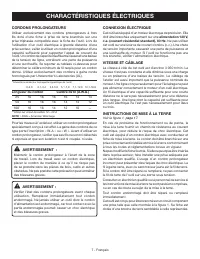
7 - Français CHARACTÉRISTIQUES ÉLECTRIQUES CONNEXION ÉLECTRIQUE Cet outil est équipé d’un moteur électrique de précision. Elle doit être branchée uniquement sur une alimentation 120 V, c.a. (courant résidentiel standard), 60 Hz. Ne pas utiliser cet outil sur une source de courant continu (c.c.). Une...
Page 24 - GLOSSAIRE
8 - Français Griffes antirebond (scies à table et radiales) Dispositifs qui, s’ils sont correctement installés et entretenus, sont conçus pour empêcher que la pièce coupée soit propulsée en direction de l’opérateur durant le sciage en long (refente). Axe Pièce sur laquelle une lame ou un outil de co...
Page 25 - CARACTÉRISTIQUES
9 - Français CARACTÉRISTIQUES Dimensions de la table ................................. 194 x 165 mm (7 - 5 / 8 in. x 6 -1 / 2 po) Mouvements de la table ............................45° à la verticale 360° à swivel Hauteur hors tout .................................... 736,6 mm (29 po) FICHE TECHNIQU...
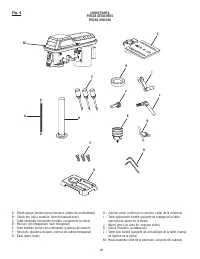
Page 26 - DÉBALLAGE; ASSEMBLAGE; OUTILS NÉCESSAIRES
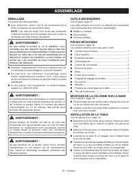
10 - Français DÉBALLAGE Ce produit doit être assemblé. Avec précaution, sortir l’outil et les accessoires de la boîte. Les placer sur une surface plane. NOTE : Cet outil est lourd. Pour éviter des problèmes lombaires soulever avec les jambes, pas avec le dos et demander de l’aide lorsque nécessair...
Page 27 - INSTALLATION DU MANDRIN, DE LA TÊTE ET
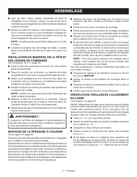
11 - Français ASSEMBLAGE Avec les deux mains, glisser l’ensemble de table et crémaillère sur la colonne, jusqu’à ce que le bas de la crémaillère soit engagé dans le collier de la base et appuyé contre la colonne. Glisser le collier de colonne, côté biseauté vers le bas, sur la colonne, jusqu’à c...
Page 28 - UTILISATION; CLÉ À MANDRIN À ÉJECTION AUTOMATIQUE
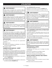
12 - Français UTILISATION AVERTISSEMENT : Ne pas laisser la familiarité avec l’outil faire oublier la prudence. Ne pas oublier qu’une fraction de seconde d’inattention peut entraîner des blessures graves. AVERTISSEMENT : Toujours porter une protection oculaire munie d’écrans latéraux certifiée confo...
Page 29 - PERÇAGE; CONSEILS POUR LE PERÇAGE
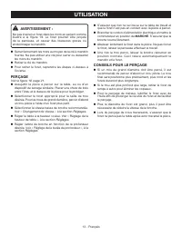
13 - Français UTILISATION AVERTISSEMENT : Ne pas insérer un foret dans les mors en serrant comme illustré à la figure 19. Le foret pourrait être projeté de la perceuse, et causer des blessures graves ou endommager le mandrin. Serrer fermement les mors au moyen de la clé à mandrin fournie. Ne pas u...
Page 30 - RÉGLAGES; RÉGLAGE DE LA HAUTEUR DE TABLE; RÉGLAGE LIMITEUR DE PROFONDEUR
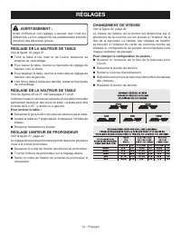
14 - Français RÉGLAGES AVERTISSEMENT : Avant d’effectuer tout réglage, s’assurer que l’outil est débranché. Le non-respect de cet avertissement pourrait entraîner des blessures graves. RÉGLAGE DE LA HAUTEUR DE TABLE Voir la figure 19, page 21. Tenir la table d’une main et de l’autre, desserrer sa ...
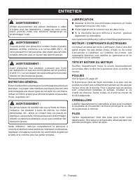
Page 31 - ENTRETIEN; TÊTE ET BOÎTIER DU MOTEUR
15 - Français ENTRETIEN AVERTISSEMENT : Utiliser exclusivement des pièces identiques à celles d’origine pour les réparations. L’usage de toute autre pièce pourrait créer une situation dangereuse ou endommager l’outil. AVERTISSEMENT : Toujours porter une protection oculaire munie d’écrans latéraux ce...
Page 32 - DÉPANNAGE; Problème
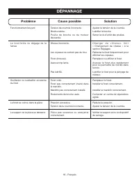
16 - Français DÉPANNAGE Problème Cause possible Solution Fonctionnement bruyant Tension de courroie incorrecte.Broche sèche.P o u l i e d e b ro c h e o u d e m o t e u r desserrée. Ajuster la tension de la courroie.Lubrifier la broche.Serrer la vis d’arrêt des poulies. Le foret brûle ou dégage de l...
Page 35 - REGLAS DE SEGURIDAD GENERALES; LEA TODAS LAS INSTRUCCIONES
3 - Español REGLAS DE SEGURIDAD GENERALES ADVERTENCIA: Lea y comprenda todas las instrucciones. El incumplimiento de cualquiera de las instrucciones señaladas abajo puede causar descargas eléctricas, incendios y lesiones corporales serias. LEA TODAS LAS INSTRUCCIONES FAMILIARÍCESE CON SU HERRAMIEN...
Page 37 - REGLAS DE SEGURIDAD ESPECÍFICAS
5 - Español REGLAS DE SEGURIDAD ESPECÍFICAS MANTENGA LAS BROCAS LIMPIAS Y AFILADAS. Las brocas afiladas reducen al mínimo los atorones. Las brocas sucias y desafiladas pueden causar la desalineación del material y posibles lesiones corporales al operador. MANTENGA LAS MANOS ALEJADAS DEL ÁREA DE ...
Page 38 - SÍMBOLOS
6 - Español SÍMBOLOS Es posible que se empleen en este producto algunos de los siguientes símbolos. Le suplicamos estudiarlos y aprender su significado. Una correcta interpretación de estos símbolos le permitirá utilizar mejor y de manera más segura el producto. SÍMBOLO NOMBRE DENOMINACIÓN/EXPLICACI...
Page 39 - CONEXIÓN ELÉCTRICA; VELOCIDAD Y CABLEADO; ASPECTOS ELÉCTRICOS
7 - Español CONEXIÓN ELÉCTRICA Esta herramienta está impulsada por un motor eléctrico fabricado con precisión. Debe conectarse únicamente a una línea de voltaje de 120 V, de corriente alterna solamente (corriente normal para uso doméstico), 60 Hz. No utilice esta herramienta con corriente continua (...
Page 40 - GLOSARIO DE TÉRMINOS
8 - Español GLOSARIO DE TÉRMINOS Trinquetes anticontragolpe (sierras radiales y de mesa) Es un dispositivo, el cual, cuando se instala y da mantenimiento correctamente, sirve para detener la pieza de trabajo para no ser lanzada hacia atrás, hacia la parte frontal la sierra durante una operación de c...
Page 41 - CARACTERÍSTICAS; LÁSER EXACTLINE; TOPE DE PROFUNDIDAD
9 - Español CARACTERÍSTICAS Carrera del husillo ................................... 50,8 mm (2 pulg.)Tamaño de la mesa 194 x 165 mm (7-5/8 in. x 6-1/2 pulg.)Movimiento de la mesa ..... 45° de inclinación, 360° de giroAltura total ........................................... 736,6 mm (29 pulg.) ESPECI...
Page 42 - DESEMPAQUETADO; ARMADO; HERRAMIENTAS NECESARIAS
10 - Español DESEMPAQUETADO Este producto requiere armarse. Extraiga cuidadosamente de la caja la herramienta y los accesorios. Colóquela sobre una superficie de trabajo nivelada. NOTA: Esta herramienta es pesada. Para evitar sufrir lesiones en la columna, levante con las piernas, no con la espald...
Page 43 - MONTAJE DE LA TALADRADORA DE COLUMNA; VERIFICACIÓN Y AJUSTE DE LA ALINEACIÓN
11 - Español ARMADO Deslice con ambas manos todo el conjunto de la mesa y la cremallera por la columna hasta que la parte inferior de la cremallera quede colocada en el collar de la base y contra la columna. Deslice el collar de la columna por ésta con el lado del bisel hacia abajo, hasta que el...
Page 44 - FUNCIONAMIENTO; USOS; ROTACIÓN DE LA MESA
12 - Español FUNCIONAMIENTO ADVERTENCIA: No permita que su familarización con las herramientas lo vuelva descuidado. Tenga presente que un descuido de un instante es suficiente para causar una lesión grave. ADVERTENCIA: Siempre utilice protección para los ojos con escudos laterales que cumplan con A...
Page 45 - MONTAJE Y DESMONTAJE DE LAS BROCAS; SUGERENCIAS PARA EL TALADRADO
13 - Español FUNCIONAMIENTO MONTAJE Y DESMONTAJE DE LAS BROCAS Vea la figura 17, página 21 . Conecte la taladradora de columna. Abra o cierre las mordazas del portabrocas hasta que la abertura sea levemente más grande que la broca deseada. Introduzca la broca en el portabrocas, en toda la p...
Page 46 - AJUSTES; AJUSTE DE LA ALTURA DE LA MESA; AJUSTE DEL CALIBRE DE PROFUNDIDAD; CAMBIO DE VELOCIDAD
14 - Español AJUSTES ADVERTENCIA: Antes de efectuar cualquier ajuste, asegúrese de que la herramienta esté desconectada del suministro de corriente. La inobservancia de esta advertencia podría causar lesiones serias. AJUSTE DE LA ALTURA DE LA MESA Vea la figura 19, página 21. Sujete la mesa con un...
Page 47 - MANTENIMIENTO
15 - Español MANTENIMIENTO ADVERTENCIA: Al dar servicio a la unidad, sólo utilice piezas de repuesto idénticas. El empleo de piezas diferentes puede causar un peligro o dañar el producto. ADVERTENCIA: Siempre utilice protección para los ojos con escudos laterales que cumplan con ANSI Z87.1. La inobs...
Page 48 - SOLUCIÓN DE PROBLEMAS; Problema
16 - Español SOLUCIÓN DE PROBLEMAS Problema Causa posible Solución Funcionamiento ruidoso. Tensión incorrecta en la correa.Está seco el husillo.Afloje la polea del husillo o la del motor. Ajuste la tensión de la correa.Lubrique el husillo.Apriete los tornillos fijadores de las poleas. La broca quema...
Page 49 - NOTAS
Page 56 - OPERATOR’S MANUAL/10 in DRILL PRESS; MANUEL D’UTILISATION / PERCEUSE À COLONNE; ou en téléphonant au
23 9900008463- 5 -14 (REV:01) OPERATOR’S MANUAL/10 in DRILL PRESS MANUEL D’UTILISATION / PERCEUSE À COLONNE DE 254 mm (10 po) MANUAL DEL OPERADOR/TALADRADORA DE COLUMNA DE 254 mm (10 pulg.) DP103L ONE WORLD TECHNOLOGIES, INC. 1428 Pearman Dairy Road, Anderson, SC 29625 • Phone 1-800-525-2579 États-U...


 Ryobi SS630
User Manual
Ryobi SS630
User Manual
 Ryobi 18A-C06-734
User Manual
Ryobi 18A-C06-734
User Manual
 Ryobi 21AB454B734
User Manual
Ryobi 21AB454B734
User Manual
 Ryobi 41CD875A034
User Manual
Ryobi 41CD875A034
User Manual
 Ryobi 767R
User Manual
Ryobi 767R
User Manual
 Ryobi 2079R
User Manual
Ryobi 2079R
User Manual
 Ryobi 725R
User Manual
Ryobi 725R
User Manual
 Ryobi 890R
User Manual
Ryobi 890R
User Manual
 Ryobi 825R
User Manual
Ryobi 825R
User Manual
 Ryobi 96116000202
User Manual
Ryobi 96116000202
User Manual