Page 2 - GENERAL POWER TOOL SAFETY WARNINGS
2 - English WARNING Read all safety warnings and all instructions. Failure to follow the warnings and instructions may result in electric shock, fire and/or serious injury. Save all warnings and instructions for future reference. The term “power tool” in the warnings refers to your mains- operated (...
Page 3 - SERVICE
3 - English SAFETY WARNINGS COMMON FOR GRIND-ING, SANDING, WIRE BRUSHING AND POLISH-ING OPERATIONS This power tool is intended to function as a grinder, sander, wire brush, or polisher. Read all safety warn- ings, instructions, illustrations and specifications provided with this power tool. Failur...
Page 4 - KICKBACK AND RELATED WARNINGS; ANGLE GRINDER SAFETY WARNINGS
4 - English Regularly clean the power tool’s air vents. The motor’s fan will draw the dust inside the housing and excessive accumulation of powdered metal may cause electrical hazards. Do not operate the power tool near flammable materials. Sparks could ignite these materials. Do not use a...
Page 5 - ADDITIONAL SAFETY RULES; CALIFORNIA PROPOSITION 65
5 - English ADDITIONAL SAFETY RULES Always use proper guard with grinding wheel. A guard protects operator from broken wheel fragments. Know your power tool. Read operator’s manual care-fully. Learn its applications and limitations, as well as the specific potential hazards related to this too...
Page 6 - SYMBOLS
6 - English The following signal words and meanings are intended to explain the levels of risk associated with this product. SYMBOL SIGNAL MEANING DANGER: Indicates an imminently hazardous situation, which, if not avoided, will result in death or serious injury. WARNING: Indicates a potentially haza...
Page 7 - EXTENSION CORDS; ELECTRICAL; DOUBLE INSULATION; ELECTRICAL CONNECTION
7 - English EXTENSION CORDS When using a power tool at a considerable distance from a power source, be sure to use an extension cord that has the capacity to handle the current the tool will draw. An undersized cord will cause a drop in line voltage, resulting in overheating and loss of power. Use t...
Page 8 - FEATURES; PRODUCT SPECIFICATIONS; ASSEMBLY; UNPACKING; INSTALLING/REPLACING GRINDING WHEEL
8 - English FEATURES PRODUCT SPECIFICATIONS Wheel Size .............................................................4-1/2 in.Wheel Thickness ...................................... 0.236 in. (6 mm)Arbor Size ................................................ 5/8 in. x 11 UNC No Load Speed ................
Page 9 - WARNING; INSTALLING THE SIDE HANDLE; OPERATION; APPLICATIONS
9 - English Unplug the angle grinder. Depress and hold the spindle lock button and rotate nut with provided wrench until spindle locks. NOTE: To prevent damage to the spindle or spindle lock, always allow motor to come to a complete stop before engaging spindle lock. Loosen and remove flange n...
Page 10 - ROTATING HANDLE; POSITIONING THE GUARD; GRINDING AND SANDING
10 - English To release the lock, depress and release the switch trigger. If the lock-on feature is engaged during use and the angle grinder becomes disconnected from the power supply, disengage the lock-on feature immediately. NOTICE: Never cover air vents. They must always be open for proper mot...
Page 11 - MAINTENANCE; GENERAL MAINTENANCE; NOTE: ILLUSTRATIONS START ON PAGE 12
11 - English MAINTENANCE WARNING: When servicing, use only identical replacement parts. Use of any other parts could create a hazard or cause product damage. WARNING: Always wear eye protection with side shields marked to comply with ANSI Z87.1. Failure to do so could result in objects being thrown ...
Page 12 - AVERTISSEMENT; SÉCURITÉ DU LIEU DE TRAVAIL; AVERTISSEMENTS DE SÉCURITÉ RELATIVES AUX OUTILS
2 - Français AVERTISSEMENT Lire tous les avertissements et toutes les instructions. Ne pas suivre l’ensemble des avertissements et des instructions peut entraîner une électrocution, un incendie ou des blessures graves. Conserver les avertissements et les instructions à des fins de référence ultérieu...
Page 13 - DÉPANNAGE; AVERTISSEMENTS DE SÉCURITÉ RELATIFS
3 - Français RÈGLES DE SÉCURITÉ GÉNÉRALES POUR LE MEULAGE, PONÇAGE, BROSSAGE MÉTALLIQUE ET POLISSAGE DES PIÈCES Cet outil électrique est conçu pour servir de meuleuse, de ponceuse, de brosse métallique ou de polisseuse. C o n s u l t e r t o u s l e s a v e r t i s s e m e n t s e t t o u t e s l ...
Page 14 - REBONDS ET AVERTISSEMENTS CONNEXES; AVERTISSEMENTS DE SÉCURITÉ RELATIFS AU
4 - Français Ne jamais déposer l’outil électrique avant l’arrêt complet de l’accessoire. L’accessoire en rotation peut attraper la surface et occasionner une perte de contrôle. Ne jamais laisser l’outil électrique fonctionner en le transportant à ses côtés. L’accessoire en rotation peut s’accroc...
Page 15 - PROPOSITION 65 DE L’ÉTAT DE CALIFORNIE
5 - Français AVERTISSEMENTS DE SÉCURITÉ PARTICULIÈRES POUR OPÉRATIONS DE LA BROSSE MÉTALLIQUE Porter une attention particulière à la brosse métallique, dont les poils peuvent être projetés même pendant une opération régulière. Éviter de surcharger les poils en appuyant sur la brosse de manière exc...
Page 16 - SYMBOLES
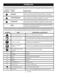
6 - Français SYMBOLES Certains des symboles ci-dessous peuvent être utilisés sur produit. Veiller à les étudier et à apprendre leur signification. Une interprétation correcte de ces symboles permettra d’utiliser produit plus efficacement et de réduire les risques. SYMBOLE NOM DÉSIGNATION / EXPLICATI...
Page 17 - CARACTÉRISTIQUES ÉLECTRIQUES; DOUBLE ISOLATION; CONNEXIONS ÉLECTRIQUES; CORDONS PROLONGATEURS
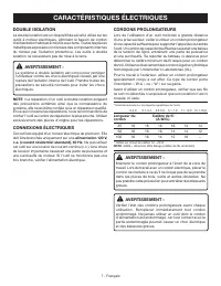
7 - Français CARACTÉRISTIQUES ÉLECTRIQUES DOUBLE ISOLATION La double isolation est un dispositif de sécurité utilisé sur les outils à moteur électriques, éliminant le besoin de cordon d’alimentation habituel à trois fils avec terre. Toutes les pièces métalliques exposées sont isolées des composants ...
Page 18 - CARACTÉRISTIQUES; FICHE TECHNIQUE; ASSEMBLAGE; DÉBALLAGE; INSTALLATION DES MEULES
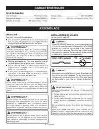
8 - Français CARACTÉRISTIQUES FICHE TECHNIQUE Taille de m eule ...................................... 115 mm (4-1/2 po) Épaisseur du disque ................................. 6 mm (0,236 in.)Diamètre de broche ................... 5/8 po (16 mm) x 11 UNC Vites se à vide ..................................
Page 19 - INSTALLATION DE LA POIGNÉE LATÉRALE; UTILISATION
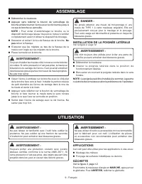
9 - Français Débrancher la meuleuse. Appuyer sans relâcher le bouton de verrouillage de broche et faire tourner l’écrou avec la clé fournie jusqu’à ce que la broche se verrouille. NOTE : Pour éviter d’endommager la broche ou le dispositif de blocage laissez toujours le moteur s’arrêter complètem...
Page 20 - POSITIONNEMENT DU GARANT; MEULAGE ET PONÇAGE
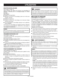
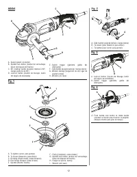
10 - Français BOUTON DE BLOCAGE Voir la figure 3, page 12. Cette meuleuse est dotée d’un bouton de verrouillage de gâchette, commode pour le meulage/ponçage en continu prolongé . Verrouillage : Appuyer sur la gâchette. Maintenir le bouton de verrouillage, situé sur le côté de la poignée, enfoncé...
Page 21 - ENTRETIEN; ENTRETIEN GÉNÉRAL; ENSEMBLES DE CHARBON; REMPLACEMENT DU GARANT; NOTE : ILLUSTRATIONS COMMENÇANT
11 - Français ENTRETIEN AVERTISSEMENT : Utiliser exclusivement des pièces d’origine pour les réparations. L’usage de toute autre pièce pourrait créer une situation dangereuse ou endommager l’outil. AVERTISSEMENT : Toujours porter une protection oculaire avec écrans latéraux certifiée conforme à la n...
Page 22 - ADVERTENCIA; ÁREA DE TRABAJO; ADVERTENCIAS DE SEGURIDAD PARA HERRAMIENTAS ELÉCTRICAS
2 - Español ADVERTENCIA L e a t o d a s l a s a d v e r t e n c i a s d e s e g u r i d a d y l a s instrucciones. La inobservancia de las advertencias e instrucciones puede causar descargas eléctricas, incendios o lesiones graves. Guarde todas las advertencias e instrucciones para consultarlas en e...
Page 24 - ADVERTENCIAS DE SEGURIDAD DE
4 - Español No haga funcionar la herramienta mientras la transporta a su costado. El contacto accidental con el accesorio en movimiento puede enganchar la ropa y hacer que el accesorio se arrastre hacia el cuerpo. Limpie regularmente las rejillas de ventilación de la herramienta eléctrica. El ...
Page 26 - SÍMBOLOS
6 - Español SÍMBOLOS Es posible que se empleen en este producto algunos de los siguientes símbolos. Le suplicamos estudiarlos y aprender su significado. Una correcta interpretación de estos símbolos le permitirá utilizar mejor y de manera más segura el producto. SÍMBOLO NOMBRE DENOMINACIÓN/EXPLICACI...
Page 27 - ASPECTOS ELÉCTRICOS; DOBLE AISLAMIENTO; CONEXIÓN ELÉCTRICA; CORDONES DE EXTENSIÓN
7 - Español ASPECTOS ELÉCTRICOS DOBLE AISLAMIENTO El doble aislamiento es una característica de seguridad de las herramientas eléctricas, la cual elimina la necesidad de usar el típico cordón eléctrico de tres conductores con conexión a tierra. Todas las partes metálicas expuestas están aisladas de ...
Page 28 - CARACTERÍSTICAS; ESPECIFICACIONES; ARMADO; DESEMPAQUETADO; INSTALACION DE LAS MUELAS
8 - Español CARACTERÍSTICAS ESPECIFICACIONES Capacidad de la muela abrasiva ...... 115 mm (4-1/2 pulg.) Espesor de la muela ................................. 6 mm (0,236 in.)Tamaño del árbol ................... 5/8 pulg. (16 mm) x 11 UNC Velocidad en vacío .....................................11 000...
Page 29 - FUNCIONAMIENTO; USOS
9 - Español ARMADO Desconecte la amoladora angular. Oprima el botón de bloqueo del husillo y gire la tuerca de presión hasta qu e el husillo quede bloqueado. NOTA: Para evitar que se dañe el husillo o el bloqueo del hussillo, siempre deje que el motor pare completemente antes de enganchar el blo...
Page 30 - BOTÓN DEL SEGURO DE ENCENDIDO; MANGO GIRATORIO DE 90 ̊; POSICIONAMIENTO DEL PROTECTOR; PELIGRO
10 - Español BOTÓN DEL SEGURO DE ENCENDIDO Vea la figura 3, págin a 12. Esta amoladora angular está equipada de un seguro de encendido, el cual es muy útil cuando se requiere un amolado/ lijado continuo durante períodos de tiempo prolongados. Para poner el seguro de encendido: Oprima el gatillo de...
Page 31 - MANTENIMIENTO; MANTENIMIENTO GENERAL; REEMPLAZO DEL PROTECTOR
11 - Español MANTENIMIENTO ADVERTENCIA: Para el servicio de la unidad sólo utilice piezas de repuesto idénticas. El empleo de piezas diferentes podría causar un peligro o dañar el producto. ADVERTENCIA: Siempre póngase protección ocular con protección lateral con la marca de cumplimiento de la norma...
Page 36 - MANUAL DEL OPERADOR / AMOLADORA ANGULAR DE 115 mm; ou en téléphonant au
9910008777-29-16 (REV:02) OPERATOR’S MANUAL / 4-1/2 in. ANGLE GRINDER MANUEL D’UTILISATION / MEULEUSE ANGULAIRE DE 115 mm (4-1/2 po) MANUAL DEL OPERADOR / AMOLADORA ANGULAR DE 115 mm (4-1/2 pulg.) AG454 RYOBI is a registered trademark of Ryobi Limited and is used pursuant to a license granted by Ryo...