Page 2 - maintenance can cause property damage, injury or death.; Keep this manual in a secure place.; And; stage Model SE Series is natural gas only
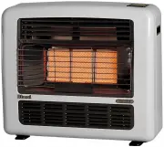
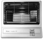
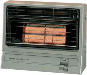
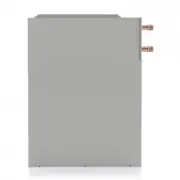
2 SE Series Infrared G as He ate r Installatio n and Operatio n Manual NOTICE: Rinnai reserves the right to make changes to equipment and specifications without obligation or notification. This publication, or parts thereof, may not be reproduced in any form, without prior written consent from Rinna...
Page 3 - TABLE OF CONTENTS; Patio Heater for Outdoor Commercial/Residential Application; VENTILATION FOR INDOOR APP’S; IMPORTANT; Installer
3 SE Series Infrared G as He ate r Installatio n and Operatio n Manual TABLE OF CONTENTS TOPIC PAGE NUMBER IMPORTANT INFORMATION - READ FIRST IM PORTANT WARNINGS ........................... 4 HEATER EXPANSION ................................ 5 GAS CONNECTION .................................... 5 VE...
Page 4 - SULATION IN THE ROOF—CONDENSATION WILL OCCUR.; WARNING; DO NOT INSTALL THIS APPLIANCE IN A RECESS, ALCOVE, OR; WARNING; WARNING
4 SE Series Infrared G as He ate r Installatio n and Operatio n Manual Improper installation, adjustment, alteration, service or maintenance can cause property damage, injury or death. Read and understand this installation and op-eration manual thoroughly prior to assembly, installation, operation o...
Page 5 - Refer to Section 14; Stainless Steel & Painted Finishes
5 SE Series Infrared G as He ate r Installatio n and Operatio n Manual Heater Expansion It is a normal condition that during heat - up and cool - down a radiant heater will expand and contract. Allowances for heater expansion must be made in the gas connection and heater suspension. Improp-er instal...
Page 6 - DO NOT INSTALL THIS APPLIANCE IN A RECESS, ALCOVE,; INSTALLATION AS AN OUTDOOR PATIO HEATER; or
6 SE Series Infrared G as He ate r Installatio n and Operatio n Manual Certain materials or items, when stored under the heater, will be subjected to radiant heat and could be seriously damaged. Location of flammable or explosive objects, liquids or vapors close to the heater may cause fire or explo...
Page 7 - It is the installer; Do not mount less than 8 ft
7 SE Series Infrared G as He ate r Installatio n and Operatio n Manual Table 1: OUTDOOR - MINIMUM MOUNTING & CLEARANCES TO COMBUSTIBLES The clearance to combustible material represents the minimum distance that must be main-tained between the outer heater surf ace and a nearby surface. In an OUT...
Page 8 - Horizontal
8 SE Series Infrared G as He ate r Installatio n and Operatio n Manual Table 2: SUGGESTED MOUNTING DISTANCES FOR COMFORT MOUNTING PARAMETERS *** MODEL RSE1S35XX 35,000 Btuh MODELS RSE1S50XX / RSE2S50XX 50,000 Btuh A - Mounting angle Horizontal 30 0 Horizontal 30 0 H - Suggested height above deck 8’ ...
Page 9 - WHEN INSTALLED INDOORS FOR COMFORT OR SPACE HEAT; It is the installer
9 SE Series Infrared G as He ate r Installatio n and Operatio n Manual WHEN INSTALLED INDOORS FOR COMFORT OR SPACE HEAT • Also refer to “ Outdoor ” definition and requirements on page 16 • And refer to Indoor Ventilation Requirements Section 14 Clearance to Combustibles Location of flammable or expl...
Page 10 - Note: Do not store or place anything directly under heater
10 SE Series Infrared G as He ate r Installatio n and Operatio n Manual Table 3: INDOOR - MINIMUM MOUNTING & CLEARANCES TO COMBUSTIBLES The clearance to combustible material represents the minimum distance that must be main- tained between the outer heater surface and a nearby surface. The state...
Page 11 - HEATER DIMENSIONS & CONFIGURATIONS; Side View; MOUNTING KIT OPTIONS; ITEM NO; Mount heater up to maximum 30° angle.
11 SE Series Infrared G as He ate r Installatio n and Operatio n Manual MODEL* Voltage VAC Current amps Btu/hr input Total W eight lbs. [kg] Length Inches [mm] RSE1S35XX 24 40 VA** 35,000 53 [24] 44” [ 1118] RSE1S50XX 24 40 VA** 50,000 57 [26] 44” [ 1118] RSE2S50XX 24 40 VA** 50,000 / 36,500 57 [26]...
Page 12 - ITEM 2: WALL MOUNT BRACKET
12 SE Series Infrared G as He ate r Installatio n and Operatio n Manual ITEM 2: WALL MOUNT BRACKET 903000022 ITEM 3: ARM MOUNTING KIT 903000028 ITEM 1: CEILING MOUNT BRACKET KIT 903000009 Also see next page ITEM 4: POST MOUNT BRACKET 903000026 CEILING MOUNT POST MOUNT ARM MOUNT WALL MOUNT Figure 5: ...
Page 13 - Stainless Steel
13 SE Series Infrared G as He ate r Installatio n and Operatio n Manual 903000009: Stainless Steel Ceiling Mount Kit for Patio Heaters Component Quantities and Material Specifications each Kit : 2 x Ceiling Bracket - 12 ga. [0.102”] 316 S/S 2 x 24” [610 MM] Channel Leg - 12 ga. [0.102”] 316 S/S 2 x ...
Page 14 - Figure 7: WALL MOUNT BRACKET
14 SE Series Infrared G as He ate r Installatio n and Operatio n Manual Figure 7: WALL MOUNT BRACKET 903000022
Page 15 - any potential snow load.; Figure 8: HEATER INSTALLATION: WALL MOUNT BRACKET
15 SE Series Infrared G as He ate r Installatio n and Operatio n Manual 1. Install the W all Mount Bracket to the structure using field supplied hardware. Ensure strength and integrity of mechanical fastening to structure for the weight of the heater and any potential snow load. 2. Install the heate...
Page 17 - INSTALLATION IN COMMERCIAL AIRCRAFT HANGARS; stalled in accordance with the latest edition of the Standard for; INSTALLATION IN COMM ERCIAL GARAGES AND PARKING STRUCTURES; Parking Structures; INSTALLATIONS OTHER THAN SPACE HEATING; PRE INSTALLATION SURVEY
17 SE Series Infrared G as He ate r Installatio n and Operatio n Manual 2. INSTALLATION IN COMMERCIAL AIRCRAFT HANGARS Luminous (high intensity) radiant tube heaters are suitable f or use in aircraft hangars when in- stalled in accordance with the latest edition of the Standard for Aircraft Hangars ...
Page 19 - DO NOT INSTALL ANY GAS PIPING IN HEAT ZONES; requires 24 Volt, 60 Hz electrical transformer sized at 40 VA.
19 SE Series Infrared G as He ate r Installatio n and Operatio n Manual 7. GAS SUPPLY PIPING • All piping must be installed according to applicable local and national codes • A listed flexible connector (field supplied) must be installed between the heater and gas supply piping. For outdoor installa...
Page 20 - NOTE: MOUNT HEATER AT MAXIMUM 30° ANGLE TO AVOID DAMAGE
20 SE Series Infrared G as He ate r Installatio n and Operatio n Manual PROPER W IRING POLARITY MUST BE MAINTAINED, particularly when grouping the heat- ers in a zone. T otal wiring distances of up to 200' must use minimum 16 gauge electrical wire, and wiring distances of over 200' must use minimum ...
Page 21 - plus; Heater/Zone Control Options; refer to section 15 page 23
21 SE Series Infrared G as He ate r Installatio n and Operatio n Manual • Install gas and electrical supplies according to all local and national codes • Mount heater up to a maximum of 30° angle on short axis using non - combustible mount- ing hardware. Refer to pages 9 to 13 in this manual for inf...
Page 24 - VENTILATION REQUIREMENTS FOR INDOOR APPLICATION; exhaust capacity requirements by the national codes in the U.S.A.; Indication of back firing:; must
24 SE Series Infrared G as He ate r Installatio n and Operatio n Manual 14. VENTILATION REQUIREMENTS FOR INDOOR APPLICATION Inadequate venting of a heater may result in asphyxiation, car-bon monoxide poisoning, injury or death. Heating system venti- lation must be in accordance with all local, state...
Page 25 - REMOTE CONTROL OPTION; USA
25 SE Series Infrared G as He ate r Installatio n and Operatio n Manual Patio Heaters can be operated using a portable Remote Control Option: • 903000030 Remote Receiver Kit (field installed in the heater) • 903000031 Remote 4 - Button Handset Transmitter • The Handset Transmitter is the master comp...
Page 27 - Single
27 SE Series Infrared G as He ate r Installatio n and Operatio n Manual Single - Stage Models only Part Number: 903000031
Page 31 - Flame Failure; SEQUENCE OF OPERATION FOR FENWAL 35; Flame current
31 SE Series Infrared G as He ate r Installatio n and Operatio n Manual Flame Failure - Re - Ignition: If the established flame signal is lost while the burner is operating, the control will respond within 0.8 seconds. The HV spark will be energized f or a trial ignition period in an attempt to reli...
Page 32 - SPARK IGNITION CIRCUIT; The step; CAUTION; control input terminals was proved, replace the ignition control.
32 SE Series Infrared G as He ate r Installatio n and Operatio n Manual 17. SPARK IGNITION CIRCUIT The step - up transformer in the ignition control provides spark ignition at 30,000 volts (open circuit). To check the spark ignition circuit, proceed as follows. 1 Shut off gas supply to the gas contr...
Page 33 - Fenwal Control Terminal Designation
33 SE Series Infrared G as He ate r Installatio n and Operatio n Manual Fault Conditions: The LED will flash on for 1/4 second, then off for 1/4 second during a fault condition. The pause between fault codes is 3 seconds. Fenwal Control Terminal Designation TH Thermostat / 24V Supply Input GND Syste...
Page 35 - Stage Switch Control; Further information
35 SE Series Infrared G as He ate r Installatio n and Operatio n Manual 18 - C. WIRING DIAGRAM: Two - Stage Switch Control Further information on 2 - Stage Control Switches - Page 41 903000006 903000007 903000008
Page 36 - TROUBLESHOOTING GUIDE; IN “SPARK IGNITION CIRCUIT”.
36 SE Series Infrared G as He ate r Installatio n and Operatio n Manual 19. TROUBLESHOOTING GUIDE TURN HEATER ON 24 VOLTS ±10% TO DSI CONTROL 24 VOLTS OUT FROM CONTROL 24 VOLTS AT GAS CONTROL SPARK ACROSS IGNITER: IS HIGH VOLTAGE SPARK OK ? MAKE SURE THE MANUAL SW ITCH ON THE GAS VALVE IS ‘ OPEN ’ A...
Page 37 - CHECK FOR CORRECT MANIFOLD GAS PRESSURE; NOTE: IF CONTROL GOES INTO LOCKOUT, THE SYSTEM CAN BE
37 SE Series Infrared G as He ate r Installatio n and Operatio n Manual MAIN BURNER LIGHTS SPARK STOPS W HEN BURNER LIT. DOES FLAME REMAIN STABLE AFTER THE SPARK CYCLE IS COM-PLETE. (NO FLAME FAIL) * CHECK FOR CORRECT MANIFOLD GAS PRESSURE *CHECK FOR OBSTRUCTION IN GAS SUPPLY OR OR- IFICE (INSECTS, ...
Page 38 - Plug; COMPLETE THIS COMMISSIONING REPORT AND; Technical commissioning report continues next page; COMMISSIONING REPORT; HEATER MODEL NUMBER :
38 SE Series Infrared G as He ate r Installatio n and Operatio n Manual 20. COMMISSIONING REPORT This heater has been factory fired and tested prior to shipment. However, it is not a ’ Plug - in ’ appliance. Commissioning and field adjustment to correct settings is required. COMPLETE THIS COMMISSION...
Page 39 - HEATER COMMISSIONING TECHNICAL REPORT; FUTURE REFERENCE
39 SE Series Infrared G as He ate r Installatio n and Operatio n Manual HEATER COMMISSIONING TECHNICAL REPORT • COMPLETE THIS COMMISSIONING REPORT AND FILE THIS MANUAL AT SITE FOR FUTURE REFERENCE • INSTRUCT THE END USER THAT THIS MANUAL MUST BE KEPT SECURE TYPE OF GAS NG LP HEATER IS EXPOSED TO CHE...
Page 40 - HIGH ALTITUDE INSTALLATION / DERATION; This heater not to be installed at altitude above 6,800 feet.; refer to information below; DO NOT
40 SE Series Infrared G as He ate r Installatio n and Operatio n Manual 21. HIGH ALTITUDE INSTALLATION / DERATION This heater not to be installed at altitude above 6,800 feet. USA: The factory installed orifice for this appliance is approved for altitudes zero to 2000 feet above sea level. When inst...
Page 41 - See; NOTE: Required Switch Sequence; Heater & switch control wiring diagrams
41 SE Series Infrared G as He ate r Installatio n and Operatio n Manual 22. CONTROL ACCESSORIES 903000006 Single Switch Gang Assembly: Control from 1 to 4 T wo - Stage Heaters in one Zone 903000007 Double Switch Gang Assembly: • Control 2 to 8 Two - Stage Heaters • 2 Zones with up to 4 heaters/zone ...
Page 42 - Heater Mounting Hardware Options; Refer to pages 11 to 15 for details; BLACK OUTDOOR; Mounts directly to top of the heater.
42 SE Series Infrared G as He ate r Installatio n and Operatio n Manual Heater Mounting Hardware Options - Refer to pages 11 to 15 for details 903000022 W ALL MOUNTING BRACKET 903000026 POST MOUNTING BRACKET (includes nuts/bolts hardware for post clamp) 903000012 3/8” X 24” BLACK OUTDOOR FLEXIBLE GA...
Page 43 - Replacement Parts List; REPLACEMENT PARTS LIST
43 SE Series Infrared G as He ate r Installatio n and Operatio n Manual 23. Replacement Parts List REPLACEMENT PARTS LIST ORDER QUANTITY RSE1S35XX RSE1S50XX, RSE2S50XX # PART NAME PART # PART # 1 Burner Body with Tiles Mounted 1 906000023 906000146 2 Orifice holder 1 906000024 906000024 3 Orifice - ...
Page 44 - STANDARD BLACK FINISH
44 SE Series Infrared G as He ate r Installatio n and Operatio n Manual REPLACEMENT PARTS LIST ORDER QUANTITY RSE1S35XX RSE1S50XX, RSE2S50XX # PART NAME PART # PART # 12 Pilot Flame Shield 1 906000036 906000036 13 DSI control FENWAL 1 905000015 905000015 14 Spark Wire - High Voltage 1 905000016 9050...
Page 45 - NOTES
45 SE Series Infrared G as He ate r Installatio n and Operatio n Manual NOTES