Rinnai RHFE-431FA - Manuals
Rinnai RHFE-431FA – Manual in PDF format online.
Manuals:
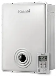
Manual Rinnai RHFE-431FA


Summary
WARNING IMPROPER INSTALLATION, ADJUSTMENT, ALTERATION,SERVICE OR MAINTENANCE CAN CAUSE PROPERTYDAMAGE, PERSONAL INJURY OR LOSS OF LIFE, REFERTO THE OWNER'S INFORMATION MANUAL PROVIDEDWITH THIS APPLIANCE. INSTALLATION AND SERVICEMUST BE PERFORMED BY A QUALIFIED INSTALLER,SERVICE AGENCY OR THE GAS SUP...
FEATURES OF THE RHFE-431FA UNITS SAFETY DEVICES – 1 – ◆ Clean Heating Forced Flue Type ◆ Easy Operation One-Touch Ignition ◆ Sensible Temperature Control Feature ◆ Comfortable Room Temperature Control and Display ◆ Warm Air Outlet at Floor Level (Keeps Your Feet Warm) ◆ Child Safety Lock ◆ Room Temp...
– 2 – Overcurrent Prevention Device: This is a 3 amp. glass fuse found on P.C. board. Design toshut unit down in case of overcurrent. If fuse blows allindicator lamps will be “OFF”. Power Outage Safety Device: This safety device cuts off gas passage and stopsoperation. Local and state codes must be ...
Rinnai Manuals
-
 Rinnai RHFE-1004FA
User Manual
Rinnai RHFE-1004FA
User Manual
-
Rinnai RHFE-1004FA
Manual
-
 Rinnai RCE-329A
User Manual
Rinnai RCE-329A
User Manual
-
Rinnai RCE-329A
Manual
-
 Rinnai RB-167RMF
Manual
Rinnai RB-167RMF
Manual
-
 Rinnai RB-207RMF
Manual
Rinnai RB-207RMF
Manual
-
 Rinnai RB-257RMF
Manual
Rinnai RB-257RMF
Manual
-
 Rinnai RB-307RMF
Manual
Rinnai RB-307RMF
Manual
-
 Rinnai RB-367RMF
Manual
Rinnai RB-367RMF
Manual
-
 Rinnai RB-106GMF/107EMF
Manual
Rinnai RB-106GMF/107EMF
Manual
-
 Rinnai RB-206GMF/207EMF
Manual
Rinnai RB-206GMF/207EMF
Manual
-
 Rinnai RB-166GMF/167EMF
Manual
Rinnai RB-166GMF/167EMF
Manual
-
 Rinnai RB-256GMF/257EMF
Manual
Rinnai RB-256GMF/257EMF
Manual
-
 Rinnai RB-306GMF/307EMF
Manual
Rinnai RB-306GMF/307EMF
Manual
-
 Rinnai RB-366GMF/367EMF
Manual
Rinnai RB-366GMF/367EMF
Manual
-
 Rinnai REH-20D
Manual
Rinnai REH-20D
Manual
-
 Rinnai EX11C (RHFE-265FTA)
Manual
Rinnai EX11C (RHFE-265FTA)
Manual
-
 Rinnai RV53I
Manual
Rinnai RV53I
Manual
-
 Rinnai REU-V2532FFU
Manual
Rinnai REU-V2532FFU
Manual
-
 Rinnai Q205S
Manual
Rinnai Q205S
Manual