Page 2 - CONTENTS
– 2 – CONTENTS Getting to Know your RHFE-308 FTR ……………………………………………………………………… 3 Remote Control ………………………………………………………………………………………………… 4 Control Panel Layout ………………………………………………………………………………………… 5 Features ………………………………………………………………………………………………………… 6 Safety Points …………………………………………………………………………………………………… 8 O...
Page 3 - GETTING TO KNOW YOUR NEW RHFE-308FTR
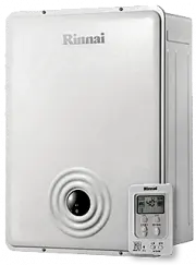
– 3 – GETTING TO KNOW YOUR NEW RHFE-308FTR REMOTE CONTROLBRACKET ROOMTEMPERATURESENSOR GAS CONNECTION ELECTRICAL CORD HUMIDIFIER TRAY Built into the warm airdischarge duct.Humidifies the warmair flow. BOTTOM TRIM Pulls off to allow fillingof humidifier tray. ON/OFF SWITCH CONTROL PANEL Concealed pan...
Page 4 - REMOTE CONTROL; FRONT; NOTE
– 4 – REMOTE CONTROL ON OFF OFF BUTTON Stops heater manually. TEMPERATURE ADJUSTMENT Increases or decreases the temperature setting. ON BUTTON Operates the heater manually. C R 2 0 3 2 OPEN TO REPLACE BATTERY Simply open the back of the remote control and replace Lithium battery. TYPE: CR 2032 BATTE...
Page 5 - CONTROL PANEL LAYOUT
– 5 – Child Lock Timer 1 Economy Timer 2 Override AM PM Set ・ Room Temp ・ Time Set times Clock Timer 1 Timer 2 Filter on off ON / OFF ON CONTROL PANEL LAYOUT ECONOMY Selects energy saving function. CHILD LOCK Locks all controls when pressed. (EXCEPT OFF) SET TIMES Selects clock and/or Timers for a...
Page 6 - WARM AIR DISCHARGE; FEATURES
– 6 – FORCED FLUE SYSTEM PUSH BUTTON IGNITION Air for combustion is taken from outside theroom and the flue products are exhaustedoutside, keeping the room air clean. Only one touch of the ON/OFF switch isrequired to operate the heater. EXHAUST AIR INLET PRE-HEAT The function will automatically ope...
Page 8 - SAFETY POINTS
– 8 – SAFETY POINTS D o n o t r e s t r i c t t h e w a r m a i r d i s c h a r g e b yplacing articles in front of the heater. T h i s a p p l i a n c e m u s t n o t b e u s e d f o r a n ypurpose other than heating. D o n o t s p r a y a e r o s o l s w h i l s t t h e h e a t e r i soperating. M...
Page 10 - OPERATING YOUR NEW RHFE-308FTR; TO OPEN THE CONTROL PANEL
– 10 – OPERATING YOUR NEW RHFE-308FTR ■ TO OPEN THE CONTROL PANEL Lift lightly in the centre of the lid where there isa catch. The control panel lid will then dropbackward to an angle. ■ TURNING ON P r e s s t h e O N / O F F b u t t o n t o o p e r a t e t h eheater. The ON indicator will glow gree...
Page 13 - FAN FILTER; HUMIDIFIER TRAY
– 13 – ■ FAN FILTER To protect the room air fan from dust particles or lint, afilter is situated at the rear of the appliance. Whenthis filter becomes blocked, the filter indicator will flashto indicate that it should be cleaned. Clean the filterw e e k l y d u r i n g t h e h e a t i n g s e a s o ...
Page 14 - SETTING THE CLOCK
– 14 – SETTING THE CLOCK When the appliance is first plugged in and then turned on, the Digital Display will show . As an example, let’s set the clock to 10:35 am. OPEN THE CONTROL PANEL - SEE PAGE 10. 1 When the appliance is first plugged in or after apower failure, the Digital Display will show . ...
Page 16 - SET AND FORGET OPERATION
– 16 – OPERATING THE TIMER(S) Before operating the Timer(s), the clock time must be correct, and a starting time and finishing time forthe Timer(s) must be programmed. See pages 14 and 15. The two Timers operate in the same way.This heater does not commence operation at the programmed starting time....
Page 19 - CARING FOR YOUR NEW RHFE-308FTR
– 19 – CARING FOR YOUR NEW RHFE-308FTR This appliance is controlled by a micro computer. If there is something wrong with the appliance thenit will stop, as it is protected by the following safety devices. Ignition Safety Device Power Failure Safety Device Burner Safety Device Power Surge Safety Dev...
Page 20 - When the unit is turned off:
– 20 – PRE-SERVICE CHECK Before asking for a service call please check the following points. These points are part of the normal operation of the unit. ■ At Ignition: Heater does not operate. Warm air does not flow when the burner lights. Smoke or strange smells are produced on the first trial light...
Page 21 - ERROR MESSAGES
– 21 – Code Displayed Fault Remedy ERROR MESSAGES The Rinnai RHFE-308FTR has the ability to check its own operation continuously. If a fault occurs, an errormessage will flash on the Digital Display of the control panel. This assists will diagnosing the fault, and mayenable you to overcome a problem...
Page 22 - INSTALLATION INSTRUCTIONS; Important Safety Instructions
– 22 – INSTALLATION INSTRUCTIONS Important Safety Instructions 1. Gas Safety (Installation & Use) Regulations 1998 are the ‘Rules in Force’. In your own interest and that of safety, it is law that all gas appliances shall be installed bycompetent persons in accordance with the above regulations....
Page 23 - Specification
– 23 – INSTALLATION INSTRUCTIONS Specification Input: 3.4kW Burner: Stainless Steel Bunsen Type Ignition: Continuous Spark Gas Inlet: 1/2 in. BSP Flue: Forced Flue (Components supplied separately.) Gas Control: Rinnai Electronic Modulating Control Electrical Supply: 230V, 50Hz. This unit has a suppl...
Page 24 - LOCATION
– 24 – LOCATION When positioning the heater the main pointsgoverning the location are: 1. Flueing 2. Warm air distribution This heater must not be installed where curtains oro t h e r c o m b u s t i b l e m a t e r i a l s c o u l d c o m e i n t ocontact with it.In some cases curtains may need res...
Page 27 - INSTALLING THE FLUE
– 27 – INSTALLING THE FLUE General. The flue must be installed in accordance with: Manufacturers Installation InstructionsBritish Standards including BS 5440 and BS EN 1319:1999Gas Safety (Installation and Use) RegulationsIGE/UP/10 Part 1 Edition 2.Building Regulation J The flue must be installed by...
Page 28 - POSITIONING THE FLUE TERMINAL
– 28 – POSITIONING THE FLUE TERMINAL O H N N M Q M H K B P Q Q I F L J G C A I D,E Dimension A B C D E F G H I J K L M N O P Q Terminal Position Directly below an opening, air brick, opening windows, etc. Above an opening, air brick, opening window, etc. Horizontally to an opening, air brick, openin...
Page 29 - SLEEVE AND MANIFOLD INSTALLATION; METHOD FOR STANDARD WALLS
– 29 – SLEEVE AND MANIFOLD INSTALLATION METHOD FOR STANDARD WALLS 1. Dis-assemble Manifold from Sleeve. T h e f l u e c o n s i s t s o f 3 p a r t s , s l e e v e , i n s i d econnectors and tube, outside terminal; (dis-assemble by pulling hard on outside terminaland inner connections, then pull sl...
Page 31 - FITTING UNIT
– 31 – FITTING UNIT AIR INLET HOSE EXHAUST PIPE & LOCKING CLAMP The following components can be fitted by reachingdown the rear of the appliance as it is positionedagainst the wall. Manifold a b Attach the Air Inlet Hose to the flue manifoldon either inlet position a or b. The unusedinlet is plu...
Page 32 - FORCED FLUE HEATER EXTENSION KITS; NAMES AND NUMBERS OF PARTS
– 32 – FORCED FLUE HEATER EXTENSION KITS • This extension set is to be used for installations requiring extra distance. MAXIMUM FLUE LENGTH 4.5m WITH 3 ELBOWS ■ NAMES AND NUMBERS OF PARTS EXTENSION KIT PARTS AND INSTALLATION GUIDE FOT - 155 0.5m EXTENSION KIT FOT - 156 1.0m EXTENSION KIT FOT - 157 2...
Page 33 - FLUE EXTENSION KITS; INSTALLING AN EXTENSION KIT FOR THE RHFE-308 FTR; HOW TO INSTALL
– 33 – FLUE EXTENSION KITS INSTALLING AN EXTENSION KIT FOR THE RHFE-308 FTR Installing an extension kit requires construction of an air line and the flue line. The air line is connectedbetween the Air Supply Elbow at the rear of the heater and the air inlet port on the Flue Pipe.Similarly, the flue ...
Page 35 - CAUTIONS
– 35 – FLUE EXTENSION KITS ■ CAUTIONS 1. Maximum extendable length F O R B E S T R O O M A I R H U M I D I T Y , K E E PWATER IN THE HUMIDIFIER TRAY. 2. To prevent water condensation Condensed watermay accumulatehere, and cause a blockagepreventing combustion. • 7.0 Metres less 1m per bend to a max ...
Page 36 - CONVERSION
– 36 – CONVERSION T h e f o l l o w i n g p r o c e d u r e m u s t b e f o l l o w e d t oconvert the unit from Nat. Gas to LPG. 1. H o l d b o t h e n d s o f t h e b o t t o m c o v e r . ( U n d e r c o v e r a s s ’ y ) a n d p u l l t o w a r d y o u t oremove the cover. Cover is snapped into ...
Page 37 - CONNECTING GAS AND ELECTRICAL SERVICES
– 37 – CONNECTING GAS AND ELECTRICAL SERVICES 1. GAS CONNECTION. Purge any air or swarf from the gas line. Connect up the appliance to the gas supply using aunion service cock to facilitate servicing.Inlet connection size Gas (1/2 inch male BSP)Check gas soundness using leak detection fluid, not nak...
Page 38 - TESTING
– 38 – TESTING Testing Unit Purge air from gas line.Refer to pipe sizing chart if in doubt about the sizeof the gas line.Connection can easily be reached from the top,rear or the unit. Check for leaks using soapy wateror leak detection spray after turning gas on. Plug unit in and turn power on, (CAU...
Page 39 - GAS PRESSURE SETTING
– 39 – GAS PRESSURE SETTING The working gas pressure on the water heater is electronically controlled and factory set. Under normalcircumstances it does not require adjustment during installation. Perform this procedure only if the unit is not operating correctly and all other possible causes for in...
Page 40 - VISUAL CHECK
– 40 – GAS PRESSURE SETTING 1. With your manometer gauge zeroed and connected to both pressure taps, press the On/Off button and operate appliance. 2. Press the SW1 test switch. 78 or 7 ≡ will be displayed on the incidator LED. 3. P r e s s t h e S W 1 s w i t c h a g a i n t o p u t t h e a p p l i...
Page 41 - FITTING TOP SPACER AND WALL CLIP
– 41 – FITTING TOP SPACER AND WALL CLIP Once Commissioning is complete the last thingto do is fix the top spacer. 1. Fit the spacer bracket to the top spacer. 2. Secure Heater to wall. Replace top spacer, clipping the spacer into thewall brackets at the same time as attaching it tothe heater. Secure...
Page 42 - BLOCK DIAGRAM
– 42 – BLOCK DIAGRAM Mark MS R, TH TF F ER TR Mark FR RC CF OH, TH OHS1, 2 FM Mark SP SV1, 2 BL RCR TB PS POV PARTS NAME MAIN SWITCH THERMISTOR THERMAL FUSE FUSE ELECTRODE TRANSFORMER PARTS NAME FLAME ROD REMOTE CONTROLLER CONVECTION FAN OVER HEAT THERMISTOR OVER HEAT SWITCH 1, 2 CONVECTION FAN MOTO...
Page 43 - WIRING DIAGRAM
– 43 – WIRING DIAGRAM 3 AC230V TB TR2 bk bk r r M r bk w PS CODE bk bl gr gr / y pk r w y gy or br lb COLOUR black blue green green/yellow pink red white yellow grey orange brown light blue RHFE-308FTR
Page 44 - DIMENSIONS
– 44 – DIMENSIONS 260 426 121 618 335 677 WALL CLIP GAS CONNECTION 165 85 25 335 11 7 (mm)
Page 45 - FLUE POSITION THROUGH WALL
– 45 – FLUE POSITION THROUGH WALL 88 425 121 616 296.5 264.5 64 83 109.5 R115 676.5 WALL OPENINGPOSITION(CENTRE OF FLUE) GAS CONNECTION
Page 46 - SPECIFICATION
– 46 – SPECIFICATION Model ........................................................................................................................................ RHFE-308 FTR Installation .................................................................................................................
Page 47 - NOTES
Page 48 - SERVICE CONTACT
– 48 – SERVICE CONTACT 308F-1092 2007.04 UK LTD. 9 Christleton CourtManor ParkRuncornCheshireWA7 1ST Tel. 01928 531870Fax. 01928 531880E-mail. [email protected]. www.rinnaiuk.com