Page 2 - TABLE OF CONTENTS; TABLE DES MATIÈRES / ÍNDICE DE CONTENIDO; INTRODUCTION; INTRODUCTION / INTRODUCCIÓN
2 Introduction ...................................................................................................................................................................... 2 Introduction / Introducción General Safety Rules ................................................................
Page 3 - GENERAL SAFETY RULES; READ ALL INSTRUCTIONS
3 GENERAL SAFETY RULES WARNING: Read and understand all instructions. Failure to follow all instructions listed below, may result in electric shock, fire and/or serious personal injury. READ ALL INSTRUCTIONS KNOW YOUR POWER TOOL. Read the operator’s manual carefully. Learn the tool’s applications ...
Page 5 - SPECIFIC SAFETY RULES
5 SPECIFIC SAFETY RULES NEVER PUT YOUR FINGERS into the dust hood or under the cutter guard. ALLOW THE CUTTER HEAD to reach full speed before using the planer. REPLACEMENT PARTS. All repairs, whether electrical or mechanical, should be made at your nearest authorized service center. DO NOT a...
Page 6 - SYMBOLS; SYMBOL NAME
6 SYMBOLS Some of the following symbols may be used on this tool. Please study them and learn their meaning. Proper interpretation of these symbols will allow you to operate the tool better and safer. Read Operator’s Manual Safety Alert No Hands Symbol SYMBOL NAME DESIGNATION/EXPLANATION Voltage Cur...
Page 7 - ELECTRICAL; ELECTRICAL CONNECTION; SPEED AND WIRING
7 ELECTRICAL ELECTRICAL CONNECTION This tool is powered by a precision-built electric motor. It should be connected to a power supply that is 120 volts, AC only (normal household current), 60 Hz. Do not operate this tool on direct current (DC). A substantial voltage drop will cause a loss of power a...
Page 8 - MOTOR SAFETY PROTECTION; MOTOR OVERLOAD PROTECTOR
8 MOTOR SAFETY PROTECTION This motor should be blown out or vacuumed frequently to prevent sawdust buildup which can interfere with normal motor ventilation. Connect this tool to a power source with the appropriate voltage for your model and a 15-amp branch circuit with a 15-amp time delay fuse or...
Page 9 - GLOSSARY OF TERMS
9 GLOSSARY OF TERMS Push Blocks (flooring and table saws) Device used to hold the workpiece during cutting opera-tions. This aid helps keep the operator’s hands well away from the blade. Push Blocks (jointer planers) Device used to feed the workpiece over the jointer planer cutter head during any op...
Page 10 - FEATURES
10 FEATURES PRODUCT SPECIFICATIONS Feed Rate ............................................................ 23.5 FPMInput .................................. 120 V, 60 Hz, AC Only, 15 AmpNo Load Speed .....................................9,000 r/min. (RPM) Max. Planing Height .............................
Page 11 - LOOSE PARTS LIST; UNPACKING; ASSEMBLY; MOUNTING THE PLANER TO WORKBENCH
11 LOOSE PARTS LIST See Figure 5, page 22. The following items are included with the tool: Key No. Description Qty. A Dust guide ...........................................................1 B Magnetic blade wrench .......................................1 C Switch key ...................................
Page 12 - CLAMPING PLANER TO WORKBENCH; INSTALLING THE DUST GUIDE
12 ASSEMBLY CLAMPING PLANER TO WORKBENCH See Figure 6, page 22. If the planer is to be used as a portable tool, it is recommended you fasten it permanently to a mounting board that can eas-ily be clamped to a workbench or other stable surface. The mounting board should be of sufficient size to avoid...
Page 13 - OPERATION; APPLICATIONS
13 OPERATION WARNING: Do not allow familiarity with tools to make you careless. Remember that a careless fraction of a second is sufficient to inflict serious injury. WARNING: Always wear eye protection with side shields marked to comply with ANSI Z87.1. Failure to do so could result in objects bein...
Page 14 - AVOIDING SNIPE; CARRIAGE LOCK
14 OPERATION AVOIDING SNIPE Snipe, or depressions made at either end of a workpiece by cutter blades, can occur when the board is not properly supported. Although snipe may be barely noticeable, it is important to keep the workpiece parallel and flat with the planer table to minimize snipe. Butting ...
Page 15 - ADJUSTING PLANING DEPTH
15 OPERATION ADJUSTING PLANING DEPTH See Figure 12, page 24. The depth adjustment crank handle is used to set the amount of wood being removed in a planing pass. Never make a planing cut deeper than 1/16 in. for hardwood up to 6 in. wide or 1/32 in. for hardwood between 6 in. and 13 in. wide. NOTE: ...
Page 16 - THICKNESS SCALE ADJUSTMENT; ADJUSTMENTS; BLADE ADJUSTMENT
16 WARNING: Before performing any adjustment, make sure the tool is unplugged from the power supply and the switch is in the OFF ( O ) position. Failure to heed this warning could result in serious personal injury. THICKNESS SCALE ADJUSTMENT See Figure 16, page 25. Located on the right front of the ...
Page 17 - MAINTENANCE; GENERAL MAINTENANCE
17 MAINTENANCE WARNING: When servicing, use only identical replacement parts. Use of any other part may create a hazard or cause product damage. WARNING: Always wear eye protection with side shields marked to comply with ANSI Z87.1 during product operation. If operation is dusty, also wear a dust ma...
Page 18 - CORD STORAGE; FRENCH AND SPANISH LANGUAGE SECTIONS.
18 MAINTENANCE CORD STORAGE See Figure 19, page 25. When not in use, the power cord should be wrapped around the planer. CAUTION: Check extension cords before each use. If damaged, replace immediately. Never use tool with a damaged cord since touching the damaged area could cause electrical shock re...
Page 19 - TROUBLESHOOTING; PROBLEM
19 TROUBLESHOOTING PROBLEM POSSIBLE CAUSE SOLUTION S n i p e ( d e p re s s i o n s a t e n d s o f workpiece) Dull cutter bladesIncorrect butted stock Unit not securely mounted Replace or turn cutter blades.Butt pieces end-to-end as they are fed into planer.Tighten lag bolts. Torn grain Too deep a ...
Page 20 - WARRANTY
20 WARRANTY Proof of purchase must be presented when requesting warranty service.Limited to RIDGID ® hand held and stationary power tools purchased 2/1/04 and after. This product is manufactured by One World Technologies, Inc. The trademark is licensed from RIDGID ® , Inc. All warranty communication...
Page 21 - RÈGLES DE SÉCURITÉ GÉNÉRALES; LIRE TOUTES LES INSTRUCTIONS
3 RÈGLES DE SÉCURITÉ GÉNÉRALES AVERTISSEMENT : Lire attentivement toutes les instructions. Le non-respect de toutes les instructions ci-dessous peut entraîner un choc électrique, un incendie et/ou des blessures graves. LIRE TOUTES LES INSTRUCTIONS V E I L L E R À B I E N C O N N A Î T R E L’ O U T...
Page 23 - RÈGLES DE SÉCURITÉ PARTICULIÈRES
5 RÈGLES DE SÉCURITÉ PARTICULIÈRES NE JAMAIS raboter plus d’une pièce à la fois. NE PAS RABOTER plus d’une pièce à la fois sur la table de la raboteuse. AVANT DE METTRE EN MARCHE, s’arrurer que toutes les vis de fixation sont bien serrées. ARRÊTER LA MACHINE et vérifier de nouveau le serrage d...
Page 24 - SYMBOLES; SYMBOLE; SYMBOLE SIGNAL
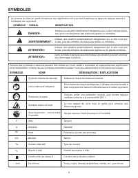
6 SYMBOLES Certains des symboles ci-dessous peuvent être utilisés sur l’outil. Veiller à les étudier et à apprendre leur signification. Une interprétation correcte de ces symboles permettra d’utiliser l’outil plus efficacement et de réduire les risques. Lire le manuel d’utilisation Symbole d’alerte ...
Page 25 - CARACTÉRISTIQUES ÉLECTRIQUES; CORDONS PROLONGATEURS; CONNEXION ÉLECTRIQUE; VITESSE ET CÂBLAGE
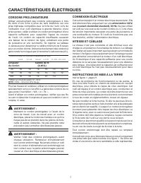
7 CARACTÉRISTIQUES ÉLECTRIQUES CORDONS PROLONGATEURS Utiliser exclusivement des cordons prolongateurs à trois fils doté d’une fiche à prise de terre brabchés sur une prise triphasée compatible avec la fiche de l’outil. Lors de l’utilisation d’un outil électrique à grande distance d’une prise secteur...
Page 26 - PROTECTION DU MOTEUR; PROTECTEUR DE SURCHAUFFE DU MOTEUR
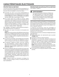
8 CARACTÉRISTIQUES ÉLECTRIQUES PROTECTION DU MOTEUR Ce moteur doit être nettoyé fréquemment pas aspiration ou jet d’air comprimé pour empêcher l’accumulation de sciure, pouvant nuire à la ventilation correcte du moteur. Connectez cet outil à une source d’alimentationà la tension appropriée pour vo...
Page 27 - GLOSSAIRE
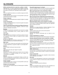
9 GLOSSAIRE Trou pilote (perceuses à colonne) Petit trou pratiqué dans une pièce servant de guide pour assurer la précision d’un trou de plus grand diamètre. Blocs poussoirs (pour scies à plancher et table) Dispositifs utilisés pour pousser le matériau contre la scie lors de la coupe. Un bâton pouss...
Page 28 - CARACTÉRISTIQUES
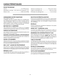
10 CARACTÉRISTIQUES FICHE TECHNIQUE Avance .................................................... 23,5 FPM (pi/min)Alimentation nominale .. 120 V, 60 Hz, CA seulement, 15 AVitesse à vide .........................................9 000 r/min (RPM) Hauteur de rabotage max ..................... 156 mm (6-...
Page 29 - LISTE DES PIÈCES DÉTACHÉE; DÉBALLAGE; ASSEMBLAGE
11 LISTE DES PIÈCES DÉTACHÉE Voir la figure 5, page 22. Les articles suivants sont inclus avec le outil : No. de Pièce Description Qté. A Guide à poussière................................................1 B Clé à lame magnétique de lame ..........................1 C Clé d’interrupteur..................
Page 30 - M O N T A G E D E L A R A B O T E U S E S U R; INSTALLATION DE LA GUIDE À POUSSIÈRE
12 ASSEMBLAGE M O N T A G E D E L A R A B O T E U S E S U R UN ÉTABLI AVEC DES SERRE-JOINTS Voir la figure 6, page 22. Si la raboteuse doit être transportée pour être utilisée à différents endroits, nous vous recommandons de la fixer de manière permanente sur un panneau de montage qui peut être faci...
Page 31 - UTILISATION; RECTIFICATION D’ÉPAISSEUR
13 UTILISATION AVERTISSEMENT : Ne pas laisser la familiarité avec l’outil faire oublier la prudence. Ne pas oublier qu’une fraction de seconde d’inattention peut entraîner des blessures graves. AVERTISSEMENT : Toujours porter une protection oculaire certifiée conforme à la norme ANSI Z87.1. Si cette...
Page 33 - RABOTAGE
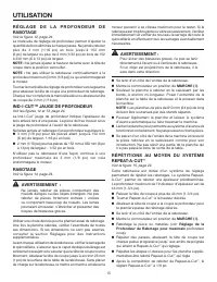
15 R É G L A G E D E L A P R O F O N D E U R D E RABOTAGE Voir la figure 12, page 24. Le manivelle de réglage de profondeur permet d’ajuster la quantité de bois éliminée à chaque passe. Ne jamais raboter plus de 3 mm (1/16 po) en bois jusqu’à 152 mm (6 po) de largeur ou plus de 2 mm (1/32 po) en boi...
Page 34 - RÉGLAGE DE L’ÉCHELLE D’ÉPAISSEUR; RÉGLAGES; RÉGLAGE DE LAME
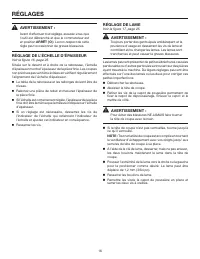
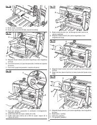
16 AVERTISSEMENT : Avant d'effectuer tout réglage, assurez-vous que l’outil est débranché et que le commutateur est en position ARRÊT ( O ) . Le non-respect de cette règle peut occasionner de graves blessures. RÉGLAGE DE L’ÉCHELLE D’ÉPAISSEUR Voir la figure 16, page 25. Située sur le devant et à dro...
Page 35 - RANGEMENT DE CLÉ DE LAME; ENTRETIEN
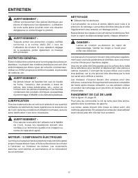
17 AVERTISSEMENT : Utiliser exclusivement des pièces identiques aux pièces d’origine pour les réparations. L’utilisation de toute autre pièce pourrait créer une situation dangereuse ou endommager le produit. AVERTISSEMENT : Toujours porter une protection oculaire certifiée conforme à la norme ANSI Z...
Page 36 - RANGEMENT DU CORDON D’ALIMENTATION; SUR 21 DE PAGE APRÈS LE SECTION ESPAGNOL.
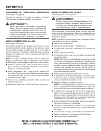
18 ENTRETIEN RANGEMENT DU CORDON D’ALIMENTATION Voir la figure 19, page 25. Lorsque la machine n’est pas en usage, le cordon d’alimentation doit être enroulé sur la raboteuse. AVERTISSEMENT : Vérifiez les cordons prolongateurs avant chaque usage. S’ils sont endommagés, remplacez-les immédiatement. N...
Page 37 - RECHERCHE DE PANNES; PROBLÈME
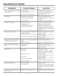
19 RECHERCHE DE PANNES PROBLÈME CAUSE POSSIBLE SOLUTION Entames (enfoncements à l’extrémité des planches rabotées) Lames émousséesAboutage des planches incorrect Machine pas solidement assujettie Remplacer ou retourner les lames.Abouter les planches à mesure de leur introduction dans la raboteuse.Se...
Page 38 - GARANTIE; RÉPARATIONS SOUS GARANTIE; AUTRES LIMITATIONS
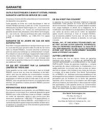
20 GARANTIE Une preuve d’achat doit être présentée pour toute demande de réparation sous garantie.Cette garantie se limite aux outils électriques à main et d’établi RIDGID ® achetés à partir du 1/2/04. Ce produit est fabriqué par One World Technologies, Inc., sous licence de marque de RIDGID ® , Inc...
Page 39 - REGLAS DE SEGURIDAD GENERALES; LEA TODAS LAS INSTRUCCIONES
3 REGLAS DE SEGURIDAD GENERALES ADVERTENCIA: Lea y comprenda todas las instrucciones. El incumplimiento de las instrucciones señaladas abajo puede causar descargas eléctricas, incendios y lesiones serias. LEA TODAS LAS INSTRUCCIONES FAMILIARÍCESE CON SU HERRAMIENTA ELÉCTRICA. Lea cuidadosamente el...
Page 40 - REGLAS DE SEGURIDAD ESPECÍFICAS
4 REGLAS DE SEGURIDAD GENERALES AVANCE LA PIEZA DE TRABAJO EN LA DIRECCIÓN CORRECTA. Solamente empuje la pieza de trabajo hacia la hoja o herramienta de corte contra el sentido de rotación de ésta. NUNCA DEJE FUNCIONANDO DESATENDIDA LA HERRAMIENTA. APAGUE LA CORRIENTE. No se aleje la herramienta...
Page 42 - SÍMBOLOS; SÍMBOLO SEÑAL
6 SÍMBOLOS Es posible que se empleen en esta herramienta algunos de los siguientes símbolos. Le suplicamos estudiarlos y aprender su significado. Una correcta interpretación de estos símbolos le permitirá utilizar mejor y de manera más segura la herramienta. SÍMBOLO NOMBRE DENOMINACIÓN/EXPLICACIÓN N...
Page 43 - ASPECTOS ELÉCTRICOS; CORDONES DE EXTENSIÓN; CONEXIÓN ELÉCTRICA; VELOCIDAD Y CABLEADO; INSTRUCCIONES DE CONEXIÓN A TIERRA
7 ASPECTOS ELÉCTRICOS CORDONES DE EXTENSIÓN Sólo utilice cordones de extensión de 3 conductores con clavijas de tres patillas y receptáculos de tres polos que acepten la clavija del cordón de la herramienta. Al utili-zar una herramienta eléctrica a una distancia consider-able del suministro de corri...
Page 44 - PROTECCIÓN DE SEGURIDAD DEL MOTOR; PROTECTOR CO
8 ASPECTOS ELÉCTRICOS PROTECCIÓN DE SEGURIDAD DEL MOTOR Este motor debe limpiarse frecuentemente aplicándole un chorro de aire o con aspiradora para evitar la acumulación de polvo de aserrín, lo cual puede interferir en la ventilación normal del motor. Conecte esta herramienta a una fuente de ener...
Page 45 - GLOSARIO DE TÉRMINOS
9 GLOSARIO DE TÉRMINOS Bloques empujadores (para sierras cortar pisos y mesa) Son dispositivos empleados para empuje la pieza de trabajo a través de la sierra durante operaciones de corte. Para las operaciones de cortes al hilo angostos debe emplearse un palo empujador. Estos medios ayudan al operad...
Page 46 - CARACTERISTICAS; CALIBRE DE PROFUNDIDAD; BOTÓN DE REAJUSTE
10 ESPECIFICACIONES DEL PRODUCTO Velocidad de Avance ................................ 23,5 FPM (PPM)Especificaciones eléctricas ................................................ .....................................120 V~, 60 Hz, sólo corr. alt., 15 AVelocidad en vacío ..................................
Page 47 - LISTA DE PIEZAS SUELTAS; DESEMPAQUETADO; ARMADO
11 LISTA DE PIEZAS SUELTAS Vea la figura 5, página 22. Los siguientes accesorios vienen incluidos con herramienta: Núm. ref. Descripción Cant. A Guía del polvo .....................................................1 B Llave magnética de la hoja ..................................1 C Llave del interrup...
Page 48 - INSTALACION DE GUÍA DEL POLVO
12 ARMADO SUJECION DE LA CEPILLO EN EL BANCO DE TRABAJO Vea la figura 6, página 22. Si la cepilladora va a ser usada como una herramienta por-tátil, recomendamos que la instale permanentemente en una tabla de montaje que pueda ser fácilmente sujetada con prensas en C en un banco de trabajo o en otra...
Page 49 - USOS; CEPILLADO DE REGRUESAMIENTO; FUNCIONAMIENTO
13 ADVERTENCIA: No permita que su familarización con las her-ramientas lo vuelva descuidado. Tenga presente que un descuido de un instante es suficiente para causar una lesión grave. ADVERTENCIA: Siempre póngase protección ocular con la marca de cumplimiento de la norma ANSI Z87.1. La in-observancia...
Page 50 - USO DE SEGURO DE LA CABEZA DEL CARRO
14 FORMA DE EVITAR EL REDONDEO DE ARISTAS El redondeo de aristas, que es una depresión hecha en cualquiera de los dos extremos de una pieza de trabajo por las cuchillas de corte, ocurre cuando no se proporciona un apoyo adecuado a la tabla. Aunque el redondeo de aristas apenas se nota, es importante...
Page 51 - CEPILLADO; R E C E P I L L A D O / U S O D E L A C U B I E R T A
15 A J U S T E D E L A P R O F U N D I D A D D E CEPILLADO Vea la figura 12, página 24. La mango de la manivela de ajuste de profundidad sirve para ajustar la cantidad de madera que va a eliminarse en cada pasada de cepillo. Nunca haga un corte que cepilla más pro-fundo que 1/16 pulg. para la madera...
Page 52 - AJUSTE DE LA ESCALA DE GROSOR; AJUSTES; AJUSTE DE LAS CUCHILLAS
16 ADVERTENCIA: Antes de efectuar cualquier ajuste, asegúrese de que la herramienta esté desconectada de la fuente de alimentación y que el interruptor esté en la posición APAGADO ( O ) . El incumplimiento de esta advertencia puede causar una lesión personal grave. AJUSTE DE LA ESCALA DE GROSOR Ver ...
Page 53 - MANTENIMIENTO
17 ADVERTENCIA: Al dar servicio a la unidad, utilice sólo piezas de repuesto idénticas. El empleo de piezas diferentes puede presentar un peligro o causar daños al producto. ADVERTENCIA: Siempre póngase protección ocular con la marca de cumplimiento de la norma ANSI Z87.1. Si la operación genera muc...
Page 54 - ALMACENAMIENTO DEL CORDÓN
18 18 MANTENIMIENTO ALMACENAMIENTO DEL CORDÓN Ver la figura 19, página 25. Cuando no está en uso la unidad, el cordón eléctrico debe enrollarse del cepillo. ADVERTENCIA: Verifique los cordones de extensión después de cada uso. Si están dañados reemplácelos inmediatamente. Nunca use la herramienta co...
Page 55 - SOLUCIÓN DE PROBLEMAS; PROBLEMA
19 SOLUCIÓN DE PROBLEMAS PROBLEMA CAUSA POSIBLE SOLUCIÓN Redondeo de aristas (despresiones en los extremos de la pieza) Cuchillas desafiladas Se metieron las tablas en fila punta con punta de forma incorrecta No está montada firmemente la unidad Reemplace o voltee las cuchillas de corte.Empuje las p...
Page 56 - GARANTÍA; LO QUE ESTÁ CUBIERTO EN LA GARANTÍA DE; LIMITACIONES ADICIONALES
20 GARANTÍA Debe presentarse prueba de la compra al solicitar servicio al amparo de la garantía.Se limita a las herramientas de mano y estacionarias RIDGID ® adquiridas a partir del 1 de febrero de 2004. Este producto está manufacturado por One World Technologies, Inc. La licencia de uso de la marca...
Page 64 - Customer Service Information:; OPERATOR’S MANUAL; Información sobre servicio al consumidor:
28 988000-297 7- 27 -16 (REV:03) Customer Service Information: For parts or service, contact your nearest RIDGID ® authorized service center. Be sure to provide all relevant information when you call or visit. For the location of the authorized service center nearest you, please call 1-866-539-1710 ...