Page 2 - Save all warnings and instructions for future reference.; WORK AREA SAFETY; Keep work area clean and well lit.; ELECTRICAL SAFETY; Do not expose power tools to rain or wet conditions.; GENERAL SAFETY RULES; PERSONAL SAFETY
2 - English WARNING: Read all safety warnings, instructions, illus-trations and specifications provided with this power tool. Failure to follow all instructions listed below may result in electric shock, fire and/or seri-ous injury. Save all warnings and instructions for future reference. The term “...
Page 3 - Keep cutting tools sharp and clean.; SERVICE; MITER SAW SAFETY RULES; the workpiece into the blade or cut “freehand” in any; Cut only one workpiece at a time.
3 - English GENERAL SAFETY RULES Disconnect the plug from the power source and/or remove the battery pack, if detachable, from the power tool before making any adjustments, changing accessories, or storing power tools. Such preventive safety measures reduce the risk of starting the power tool acci...
Page 4 - Save these instructions.; ADDITIONAL SAFETY RULES; Use the proper extension cord.
4 - English MITER SAW SAFETY RULES Provide adequate support such as table extensions, saw horses, etc. for a workpiece that is wider or longer than the table top. Workpieces longer or wider than the miter saw table can tip if not securely supported. If the cut-off piece or workpiece tips, it can...
Page 6 - SYMBOLS
6 - English Some of the following symbols may be used on this tool. Please study them and learn their meaning. Proper interpretation of these symbols will allow you to operate the tool better and safer. SYMBOL NAME DESIGNATION/EXPLANATION Safety Alert Indicates a potential personal injury hazard. Re...
Page 7 - Cord Length; ELECTRICAL; DOUBLE INSULATION; ELECTRICAL CONNECTION; power supply that is 120 V, AC only (normal; EXTENSION CORDS
7 - English When working outdoors with a product, use an extension cord that is designed for outside use. This type of cord is designated with “WA” or “W” on the cord’s jacket.Before using any extension cord, inspect it for loose or ex-posed wires and cut or worn insulation. **Ampere rating (on prod...
Page 8 - GLOSSARY OF TERMS
8 - English GLOSSARY OF TERMS Pilot Hole (drill presses and scroll saws) A small hole drilled in a workpiece that serves as a guide for drilling large holes accurately or for insertion of a scroll saw blade. Push Blocks (jointer planers) Device used to feed the workpiece over the jointer planer cutt...
Page 9 - FEATURES; PRODUCT SPECIFICATIONS
9 - English FEATURES Fig. 1 PRODUCT SPECIFICATIONS Blade Diameter ............................................................10 in.Arbor Hole ................................................................. 5/8 in.No Load Speed ........................................5,000/min. (RPM)Input ...........
Page 11 - OFF
11 - English 33.9 22.5 FEATURES MITER LOCK LEVER See Figure 4. The miter lock lever securely locks the saw at the desired miter angle. Push the lever down to lock the saw in place. To release the saw, lift the miter lock lever and depress the detent release button. POSITIVE STOPS ON MITER TABLE Posi...
Page 12 - TOOLS NEEDED; LOOSE PARTS
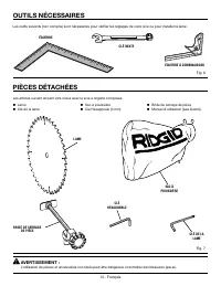
12 - English The following tools (not included) are needed for making adjustments: COMBINATION SQUARE COMBINATION WRENCH SQUARE HEX KEY TOOLS NEEDED Fig. 6 The following items are included with your Compound Miter Saw: Fig. 7 WARNING: The use of attachments or accessories not listed might be hazardo...
Page 13 - ASSEMBLY; UNPACKING
13 - English Fig. 8 ASSEMBLY UNPACKING This product requires assembly. Carefully lift saw from the carton by the carrying handle and the saw base, and place it on a level work surface. WARNING: Do not use this product if any parts on the Loose Parts List are already assembled to your product when ...
Page 14 - MOUNTING HOLES
14 - English 33.9 22.5 ASSEMBLY MOUNTING HOLES See Figure 8. WARNING: Before starting any cutting operation, clamp or bolt your miter saw to a workbench or an approved mi- ter saw stand. If a miter saw stand is used, read op- erator’s manual and follow the instructions for the miter saw stand. Never...
Page 15 - To install the work clamp:; TO INSTALL THE BLADE
15 - English ASSEMBLY To install the work clamp: Place the shaft of the work clamp in either hole on the miter table base. Rotate the knob on the work clamp to move it in or out as needed. TO INSTALL THE BLADE See Figure 12. WARNING: A 10 in. blade is the maximum blade capacity of the saw. Never...
Page 16 - LOCKING/UNLOCKING THE SAW ARM; To unlock and raise the saw arm:
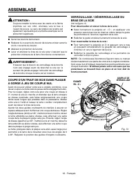
16 - English Lower the blade guard. Raise and lower the saw arm to ensure lower blade guard functions correctly. WARNING: Make sure the spindle lock button is not engaged before reconnecting saw into power source. Never engage spindle lock button when blade is rotating. CUTTING A SLOT IN THE ZER...
Page 17 - SQUARING THE BLADE TO THE FENCE
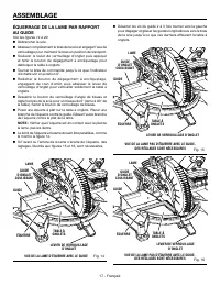
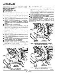
17 - English 22.5 22.5 22.5 ASSEMBLY Fig. 14 VIEW OF BLADE NOT SQUARE WITH FENCE, ADJUSTMENTS ARE REQUIRED Fig. 15 SQUARING THE BLADE TO THE FENCE See Figures 14 - 20. Unplug the saw. Pull the saw arm all the way down and engage the lock pin to hold the saw arm in transport position. Lift the ...
Page 19 - SQUARING THE BLADE TO THE MITER TABLE; To square the blade at 0°:; To square the blade at 45°:
19 - English 22.5 22.5 22.5 ASSEMBLY SQUARING THE BLADE TO THE MITER TABLE See Figures 21 - 23. To square the blade at 0°: Unplug the saw. Pull the saw arm all the way down and engage the lock pin to hold the saw arm in transport position. Lift the miter lock lever, then depress and hold the d...
Page 20 - APPLICATIONS; OPERATION; LED LIGHTING SYSTEM
20 - English WARNING: Do not allow familiarity with tools to make you careless. Remember that a careless fraction of a second is sufficient to inflict severe injury. WARNING: Always wear eye protection with side shields marked to comply with ANSI Z87.1. Failure to do so could result in objects being...
Page 21 - TO MITER CUT/CROSS CUT
21 - English 33.9 22.5 33.9 22.5 Fig. 25 CROSS CUT OPERATION Bring the saw arm down so the blade is approximately 1/4 in. from the workpiece. The shadow of the blade will be projected onto the workpiece, indicating where the blade teeth will make contact as the cut is made. TO MITER CUT/CROSS CUT Se...
Page 22 - WORK; TO BEVEL CUT; BEVEL CUT
22 - English 33.9 33.9 22.5 22.5 OPERATION WORK CLAMP Fig. 26 MITER CUT TO BEVEL CUT See Figures 27 - 28. A bevel cut is made by cutting across the grain of the workpiece with the blade angled to the workpiece. A straight bevel cut is made with the miter table set at the zero degree position and the...
Page 23 - TO COMPOUND MITER CUT
23 - English 48 45 33.9 OPERATION TO COMPOUND MITER CUT See Figure 29. A compound miter cut is a cut made using a miter angle and a bevel angle at the same time. This type of cut is used to make picture frames, cut molding, make boxes with sloping sides, and for certain roof framing cuts. To make th...
Page 24 - TO SUPPORT LONG WORKPIECES; MUST
24 - English OPERATION Release the switch trigger and allow the saw blade to stop rotating before raising the blade out of workpiece and removing the workpiece from the miter table. TO SUPPORT LONG WORKPIECES See Figure 30. Long workpieces need extra supports. Supports, roller stand, or work surfa...
Page 25 - CUTTING COMPOUND MITERS; PITCH
25 - English OPERATION CUTTING COMPOUND MITERS To aid in making the correct settings, the compound angle setting chart below has been provided. Since compound cuts are the most difficult to accurately obtain, trial cuts should be made in scrap material, and much thought and planning made, prior to m...
Page 26 - CUTTING CROWN MOLDING
26 - English Fig. 33 set the bevel angle to 33.9°. The miter angle should be set at 31.6° either right or left, depending on the desired cut for the application. See the chart below for correct angle settings and correct positioning of crown molding on miter table.The settings in the chart below can...
Page 27 - Do not overtighten as
27 - English Fig. 34 CROWN MOLDING NESTED AGAINST FRONT FACING MITER FENCE OPERATION NESTING CROWN MOLDING AGAINST THE MITER FENCE See Figures 34 - 40. To nest pieces of crown molding less than 4-5/8 in. tall: Set the bevel angle at 0° and the miter angle at 45° to either the left or the right. ...
Page 29 - Do not remove; CUTTING WARPED MATERIAL
29 - English OPERATION Fig. 42 Fig. 41 WARNING: To avoid a kickback and to avoid serious personal injury, never position the concave edge of bowed or warped material against the fence. To install the sliding miter fences in their normal operat-ing position: Loosen the fence screw and slide the mit...
Page 30 - ADJUSTMENTS; PIVOT ADJUSTMENTS; AUTHORIZED SERVICE CENTER.; TO ADJUST THE BEVEL PIVOT; AUTHORIZED SERVICE; 5° BEVEL ADJUSTMENT; LOCK NUT
30 - English 33.9 33.9 22.5 22.5 33.9 48 ADJUSTMENTS WARNING: Before performing any adjustment, make sure the tool is unplugged from the power supply. Failure to heed this warning could result in serious personal injury. The compound miter saw has been adjusted at the fac-tory for making very accura...
Page 31 - ° BEVEL ADJUSTMENT; ° BEVEL
31 - English 33.9 45 48 ADJUSTMENTS 0° BEVEL ADJUSTMENT See Figure 44. NOTE: These adjustments were made at the factory and normally do not require readjustment. Unplug the saw. Loosen the bevel lock knob by turning the knob counter- clockwise. Square the blade to the miter table as described ...
Page 32 - TO ADJUST THE MITER LOCK LEVER
32 - English 33.9 22.5 Fig. 45 Fig. 46 ADJUSTMENTS TO ADJUST THE MITER LOCK LEVER See Figures 45 - 46. When locked in an “unindexed” miter position, the miter lock lever should feel tight and secure, and considerable effort should be required to move the miter table. If the miter lock lever feels lo...
Page 33 - Proceed as follows when replacement is required:; MAINTENANCE; BRUSH CAP
33 - English WARNING: When servicing, use only identical replacement parts. Use of any other part can create a hazard or cause product damage. WARNING: Always wear eye protection with side shields marked to comply with ANSI Z87.1 during product operation. If operation is dusty, also wear a dust mask...
Page 34 - LED LENS; ACCESSORIES; CLEANING THE LED LENS; COTTON
34 - English LED LENS ACCESSORIES Look for these accessories where you purchased this product or call 1-866-539-1710: AC9946 Miter Saw Utility Vehicle ....................................................................................................................... 994670001 Dust Bag Assemb...
Page 35 - WARRANTY; RIDGID
35 - English WARRANTY Proof of purchase must be presented when requesting warranty service.Limited to RIDGID ® hand held and stationary power tools purchased 2/1/04 and after. This product is manufactured by TTI Consumer Power Tools, Inc. The trademark is licensed from RIDGID ® , Inc. All warranty c...
Page 36 - SÉCURITÉ DU LIEU DE TRAVAIL; SÉCURITÉ ÉLECTRIQUE; RÈGLES DE SÉCURITÉ GÉNÉRALES; SÉCURITÉ PERSONNELLE
2 - Français AVERTISSEMENT : Lire les avertissements de sécurité, les instructions et les précisions et consulter les illustrations fournis avec cet outil électrique. Le fait de ne pas se conformer à l’ensemble des consignes présentées ci-dessous risque d’entraîner des décharges électriques, un ince...
Page 37 - DÉPANNAGE; RÈGLES DE SÉCURITÉ DU SCIE À ONGLETS
3 - Français RÈGLES DE SÉCURITÉ GÉNÉRALES Ranger les outils motorisés hors de la portée des enfants et ne laisser personne n’étant pas familiarisé avec l’outil ou ces instructions utiliser l’outil. Dans les mains de personnes n’ayant pas reçu des instructions adéquates, les outils sont dangereux...
Page 38 - RÈGLES DE SÉCURITÉ SUPPLÉMENTAIRES
4 - Français RÈGLES DE SÉCURITÉ DU SCIE À ONGLETS S’assurer que la scie à onglets est montée ou placée à niveau sur une surface de travail ferme avant de l’utiliser. Une surface de travail ferme et à niveau réduit le risque que la scie à onglets devienne instable. Planifier votre travail. Chaque...
Page 40 - SYMBOLES
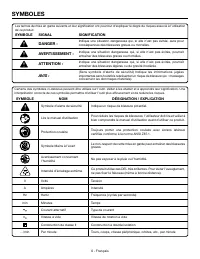
6 - Français Certains des symboles ci-dessous peuvent être utilisés sur l’outil. Veiller à les étudier et à apprendre leur signification. Une interprétation correcte de ces symboles permettra d’utiliser l’outil plus efficacement et de réduire les risques. SYMBOLE NOM DÉSIGNATION / EXPLICATION Symbol...
Page 41 - CARACTÉRISTIQUES ÉLECTRIQUES; DOUBLE ISOLATION; CONNEXIONS ÉLECTRIQUES; CORDONS PROLONGATEURS
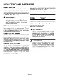
7 - Français CARACTÉRISTIQUES ÉLECTRIQUES DOUBLE ISOLATION La double isolation est un dispositif de sécurité utilisé sur les outils à moteur électriques, éliminant le besoin de cordon d’alimentation habituel à trois fils avec terre. Toutes les pièces métalliques exposées sont isolées des composants ...
Page 42 - GLOSSAIRE
8 - Français GLOSSAIRE Trou pilote (perceuses à colonne et scie à découper) Petit trou pratiqué dans une pièce servant de guide pour assurer la précision d’un trou de plus grand diamètre ou pour l’insertion d’une lame de scie à découper. Blocs poussoirs (pour dégauchisseuses/raboteuses) Dispositifs ...
Page 43 - CARACTÉRISTIQUES; FICHE TECHNIQUE
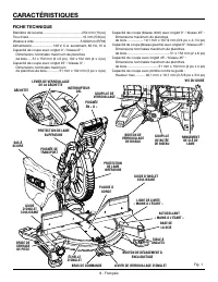
9 - Français Fig. 1 CARACTÉRISTIQUES FICHE TECHNIQUE Diamètre de la lame......................................... 254 mm (10 po)Trou d’axe ......................................................... 16 mm (5/8 po) Vitesse à vide ................................................. 5 000/min (RPM) Aliment...
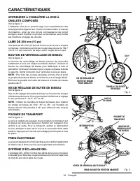
Page 44 - BOUTON DE VERROUILLAGE DE BISEAU; VIS DE RÉGLAGE DE BUTÉE DE BISEAU; POIGNÉE DE TRANSPORT; FREIN ÉLECTRIQUE
10 - Français CARACTÉRISTIQUES APPRENDRE À CONNAÎTRE LA SCIE À ONGLETS COMPOSÉS Voir la figure 1. L’utilisation sûre de ce produit exige une compréhension des renseignements figurant sur l’outil et contenus dans le manuel d’utilisation, ainsi qu’une bonne connaissance du projet entrepris. Avant d’ut...
Page 45 - LEVIER DE VERROUILLAGE D’ONGLET; BUTÉES POSITIVES DE LA TABLE À ONGLETS; BOUTON DE VERROUILLAGE DE BROCHE
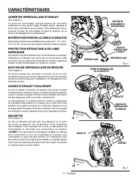
11 - Français CARACTÉRISTIQUES LEVIER DE VERROUILLAGE D’ONGLET Voir la figure 4. Le levier de verrouillage d’onglet permet de verrouiller solidement la scie selon l’angle d’onglet désiré. Abaisser le levier pour verrouiller la scie en place. Pour débloquer la scie, soulever le levier de ver...
Page 47 - ASSEMBLAGE; DÉBALLAGE
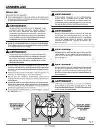
13 - Français Fig. 8 ASSEMBLAGE DÉBALLAGE Ce produit doit être assemblé. Sortir soigneusement la scie du carton en la tenant par la poignée de transport et la base de la scie, et la poser sur un plan de travail horizontal. AVERTISSEMENT : Ne pas utiliser le produit si, en le déballant, vous consta...
Page 48 - TROUS DE FIXATION; CLÉ DE LAME
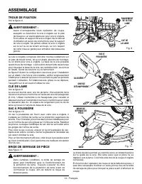
14 - Français 33.9 22.5 ASSEMBLAGE TROUS DE FIXATION Voir la figure 8. AVERTISSEMENT : Avant d’entreprendre toute opération de coupe, assujettir ou boulonner la scie à onglets sur le plan de travail ou un stand approuvé pour scie à onglets. Si on utilise un support de scie à onglet, lire le ma...
Page 49 - INSTALLATION DE LA LAME
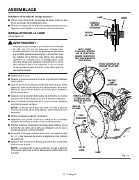
15 - Français RONDELLE DE LAME EXTÉRIEURE AVEC DOUBLES MÉPLATS EN « D » ASSEMBLAGE Installation de la bride de serrage de pièce : Placer l’axe de la bride de serrage de pièce dans un des trous de la base de la table de la scie. Tourner le bouton de la bride de serrage de pièce pour la déplacer v...
Page 54 - UTILISATION; SYSTÈME D’ÉCLAIRAGE DEL
20 - Français AVERTISSEMENT : Ne pas laisser la familiarité avec l’outil faire oublier la prudence. Ne pas oublier qu’une fraction de seconde d’inattention peut entraîner des blessures graves. AVERTISSEMENT : Toujours porter une protection oculaire avec écrans latéraux certifiée conforme à la norme ...
Page 56 - COUPE EN BISEAU
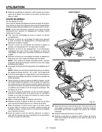
22 - Français UTILISATION Relâcher la gâchette et attendre l’arrêt complet de la lame avant de la relever de la pièce et de retirer la pièce de la table à onglet. COUPE EN BISEAU Voir les figures 27 et 28. Une coupe en biseau est réalisée en travers du grain de la pièce, avec la lame en biais. ...
Page 57 - COUPE D’ONGLET COMPOSÉ
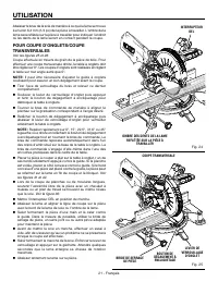
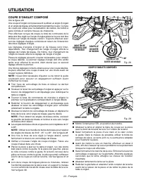
23 - Français UTILISATION COUPE D’ONGLET COMPOSÉ Voir la figure 29. Une coupe d’onglet composé revient à utiliser un angle d’onglet et un angle de biseau simultanément pendant la coupe. Ce type de coupe est utilisé pour la réalisation de cadres, de boîtes à pans inclinés et certains travaux de charp...
Page 58 - SUPPORT DE PIÈCES LONGUES
24 - Français Fig. 30 33.9 33.9 22.5 22.5 33.9 33.9 22.5 22.5 UTILISATION SUPPORT DE PIÈCES LONGUES Voir la figure 30. Les pièces longues nécessitent un support additionnel. Les supports, un support à rouleau, ou une surface de travail de niveau avec la table de la scie doivent être placés sous la p...
Page 59 - COUPE D’ONGLETS COMPOSÉS; ANGLE
25 - Français UTILISATION COUPE D’ONGLETS COMPOSÉS Le tableau des réglages d’angles ci-dessous est conçu pour faciliter les réglages. Les coupes composées étant les plus difficiles à réaliser, des essais doivent être effectués sur des chutes et la coupe définitive ne doit être effectuée qu’après mûr...
Page 60 - COUPE DE MOULURE COURONNÉE
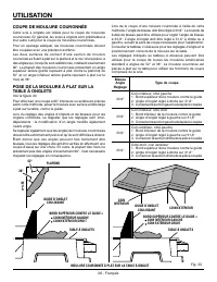
26 - Français Lors de la coupe d’une moulure couronnée à l’aide de cette méthode, l’angle de biseau doit être réglé à 33,9°. La tourelle de butée de biseau peut être utilisée pour régler l’angle de biseau à 33,9°. L’angle d’onglet doit être réglé à 31,6° à droite ou à gauche, suivant le sens de coup...
Page 61 - BORD INFÉRIEUR CONTRE LE GUIDE =
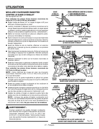
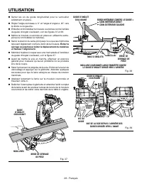
27 - Français UTILISATION MOULURE COURONNÉE EMBOÎTÉE CONTRE LE GUIDE D’ONGLET Voir les figures 34 a 40. Pour emboîter les pièces d’une moulure couronnée de moins de 117,5 mm (4 5/8 po) de hauteur : Régler l’angle de biseau à 0° et l’angle d’onglet à 45° pour effectuer un biseau gauche ou droit....
Page 63 - COUPE DE PIÈCES VOILÉES
29 - Français UTILISATION Si une pièce voilée est placée dans le mauvais sens, comme le montre la figure 41, elle pincera la lame vers la fin de la coupe. AVERTISSEMENT : Pour éviter les risques de rebond et de blessures graves, ne jamais placer le bord concave d’une pièce voilée ou déformée contre ...
Page 64 - RÉGLAGES; RÉGLAGES DES PIVOTS; RÉGLAGE DU PIVOT DE BISEAU; RÉGLAGE DU BISEAU À 45°
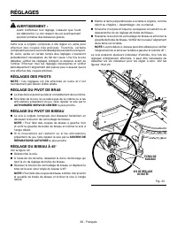
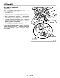
30 - Français RÉGLAGES AVERTISSEMENT : Avant d’effectuer tout réglage, s’assurer que l’outil est débranché. Le non respect de cet avertissement pourrait entraîner des blessures graves. Cette scie à onglets composés a été réglée en usine pour effectuer des coupes très précises. Toutefois, cert...
Page 65 - RÉGLAGE DU BISEAU À 0°
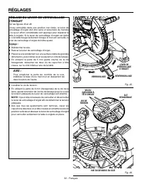
31 - Français RÉGLAGES RÉGLAGE DU BISEAU À 0° Voir la figure 44. NOTE : Ces réglages ont été effectués en usine et n’ont normalement pas besoin d’être refaits. Débrancher la scie. Desserrer le bouton de verrouillage d’angle de biseau en le tournant dans le sens inverse des aiguilles d’une montre...
Page 67 - ENTRETIEN
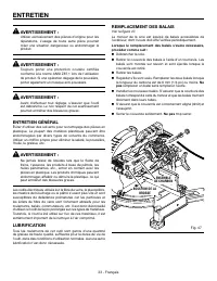
33 - Français AVERTISSEMENT : Utiliser exclusivement des pièces d’origine pour les réparations. L’usage de toute autre pièce pourrait créer une situation dangereuse ou endommager le produit. AVERTISSEMENT : Toujours porter une protection oculaire certifiée conforme à la norme ANSI Z87.1 lors de l’ut...
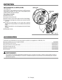
Page 68 - NETTOYAGE DE LA LENTILLE DEL
34 - Français ACCESSOIRES Rechercher ces accessoires où vous avez acheté ce produit ou en appelant au 1-866-539-1710 : Chariot utilitaire pour scie à onglets AC9946 .............................................................................................................. 994670001 Ensemb...
Page 69 - GARANTIE; RÉPARATIONS SOUS GARANTIE; AUTRES LIMITATIONS
35 - Français GARANTIE Une preuve d’achat doit être présentée pour toute demande de réparation sous garantie.Cette garantie se limite aux outils électriques à main et d’établi RIDGID ® achetés à partir du 1/2/04. Ce produit est fabriqué par TTI Consumer Power Tools, Inc., sous licence de marque de R...
Page 70 - ÁREA DE TRABAJO; SEGURIDAD ELÉCTRICA; REGLAS DE SEGURIDAD GENERALES; SEGURIDAD PERSONAL
2 - Español ADVERTENCIA: Lea todas las advertencias, instrucciones, ilustraciones y especificaciones proporcionadas con esta herramienta eléctrica. No seguir las instrucciones indicadas a continuación puede provocar descargas eléctricas, incendios o lesiones graves. Guarde todas las advertencias e i...
Page 71 - SERVICIO; REGLAS DE SEGURIDAD DE LA SIERRA INGLETEADORA
3 - Español REGLAS DE SEGURIDAD GENERALES No utilice la herramienta si el interruptor no enciende o no apaga. Cualquier herramienta eléctrica que no pueda controlarse con el interruptor es peligrosa y debe repararse. Desconecte el enchufe de la fuente de alimentación o retire el paquete de bater...
Page 73 - ADVERTENCIAS DE SEGURIDAD ADICIONALES
5 - Español Siempre póngase protección ocular con protección lateral con la marca de cumplimiento de la norma ANSI Z87.1 junto con protección para los oídos. La inobservancia de esta advertencia puede causar el lanzamiento de objetos a los ojos, y por consecuencia posibles lesiones serias. No se...
Page 74 - SÍMBOLOS
6 - Español Es posible que se empleen en esta herramienta algunos de los siguientes símbolos. Le suplicamos estudiarlos y aprender su significado. Una correcta interpretación de estos símbolos le permitirá utilizar mejor y de manera más segura la herramienta. SÍMBOLO NOMBRE DENOMINACIÓN/EXPLICACIÓN ...
Page 75 - ASPECTOS ELÉCTRICOS; DOBLE AISLAMIENTO; CONEXIÓN ELÉCTRICA; CORDONES DE EXTENSIÓN; Longitud
7 - Español ASPECTOS ELÉCTRICOS DOBLE AISLAMIENTO El doble aislamiento es una característica de seguridad de las herramientas eléctricas, la cual elimina la necesidad de usar el típico cordón eléctrico de tres conductores con conexión a tierra. Todas las partes metálicas expuestas están aisladas de ...
Page 76 - GLOSARIO DE TÉRMINOS
8 - Español GLOSARIO DE TÉRMINOS Agujero guía (taladradoras de columna y sierras caladoras) Es un agujero pequeño taladrado en una pieza de trabajo, el cual sirve como guía para taladrar con precisión agujeros más grandes o para la colocación de la hoja de la sierra caladora. Bloques empujadores (pa...
Page 77 - CARACTERÍSTICAS; ESPECIFICACIONES DEL PRODUCTO
9 - Español CARACTERÍSTICAS ESPECIFICACIONES DEL PRODUCTO Diámetro de la hoja ..................................... 254 mm (10 pulg.)Orificio del eje ............................................... 16 mm (5/8 pulg.)Velocidad en vacío ........................................5 000/min. (RPM)Corriente ...
Page 78 - PERILLA DE FIJACIÓN DE BISEL; TORNILLO DE AJUSTE DEL TOPE DE BISEL; MANGO DE ACARREO
10 - Español CARACTERÍSTICAS FAMILIARÍCESE CON LA SIERRA INGLETEADORA COMPUESTA Vea la figura 1. El uso seguro que este producto requiere la comprensión de la información impresa en la herramienta y en el manual del operador así como ciertos conocimientos sobre el proyecto a realizar. Antes de usar ...
Page 79 - PALANCA DE SEGURIDAD DE INGLETE
11 - Español 33.9 22.5 CARACTERÍSTICAS PALANCA DE SEGURIDAD DE INGLETE Vea la figura 4. La palanca de seguridad de inglete asegura la sierra en el ángulo de inglete deseado. Apriete la palanca hacia abajo para asegurar la sierra en el lugar. Para soltar la sierra, levante la palanca de seguridad de ...
Page 81 - ARMADO; DESEMPAQUETADO
13 - Español ARMADO DESEMPAQUETADO Este producto requiere armarse. Levante cuidadosamente de la caja la sierra sujetándola del mango de acarreo y de la base, y colóquela sobre una superficie de trabajo a nivel. ADVERTENCIA: No utilice este producto si alguna pieza incluida en la lista de piezas su...
Page 82 - AGUJEROS DE MONTAJE
14 - Español 33.9 22.5 ARMADO AGUJEROS DE MONTAJE Vea la figura 8. ADVERTENCIA: Antes de iniciar cualquier operación de corte, sujete con prensa(s) o atornille la sierra ingleteadora al banco de trabajo o pedestal para sierra ingleteadora aprobado. Si se utiliza un pedestal para sierra ingleteadora,...
Page 83 - PARA INSTALAR LA HOJA
15 - Español ARMADO Para instalar la prensa de trabajo: Coloque el vástago de la prensa de trabajo en un agujero u otro de la base de la mesa de la sierra. Gire la perilla de la prensa de trabajo para acercarla o alejarla, según sea necesario. PARA INSTALAR LA HOJA Vea la figura 12. ADVERTENCIA:...
Page 86 - ESCUADRADO DE LA HOJA CON LA MESA
18 - Español ARMADO Quite las guías de ingletes deslizables tirando hacia adelante y hacia atrás de la mesa de ingletes. Usando la llave para la hoja , afloje los tornillos de cabeza hueca que aseguran la guía a la mesa de ingletes. Vea la figura 18 . Gire la guía hacia la izquierda o hacia la...
Page 88 - FUNCIONAMIENTO; SISTEMA DE ILUMINACIÓN LED
20 - Español ADVERTENCIA: No permita que su familarización con las herramientas lo vuelva descuidado. Tenga presente que un descuido de un instante es suficiente para causar una lesión grave. ADVERTENCIA: Siempre póngase protección ocular con protección lateral con la marca de cumplimiento de la nor...
Page 89 - PARA REALIZAR CORTES DE INGLETE/
21 - Español 33.9 22.5 PRENSA DE TRABAJO FUNCIONAMIENTO Baje el brazo de la sierra para que la hoja se encuentre aproximadamente a 6,35 mm (1/4 pulg.) de la pieza de trabajo. La sombra de la hoja se proyectará en la pieza de trabajo, indicando dónde hará contacto el diente de la hoja cuando se reali...
Page 90 - PARA CORTAR A BISEL; PARA CORTAR INGLETES COMPUESTOS
22 - Español 33.9 33.9 22.5 22.5 FUNCIONAMIENTO Suelte el gatillo del interruptor y espere a que la hoja de la sierra deje de girar antes de levantarla de la pieza de trabajo y retirar la pieza de trabajo de la mesa de ingletes. PARA CORTAR A BISEL Vea las figuras 27 y 28. Un corte en bisel se efe...
Page 92 - APOYE LAS PIEZAS DE TRABAJO LARGAS
24 - Español 33.9 33.9 22.5 22.5 33.9 33.9 22.5 22.5 FUNCIONAMIENTO APOYE LAS PIEZAS DE TRABAJO LARGAS Vea la figura 30. Las piezas de trabajo largas necesitan soportes extra. Los soportes base con ruedas, o superficie de trabajo nivelada con la sierra de mesa deben colocarse a lo largo de la pieza ...
Page 93 - CÓMO EFECTUAR CORTES A INGLETE COMBINADOS; INCLINACIÓN
25 - Español FUNCIONAMIENTO CÓMO EFECTUAR CORTES A INGLETE COMBINADOS Como ayuda para realizar los ajustes correctos, se suministra la siguiente tabla de ángulos combinados. Puesto que los cortes combinados son los más difíciles de obtener, deben efectuarse cortes de prueba en material de desecho, a...
Page 94 - CÓMO CORTAR MOLDURAS DE CORONA
26 - Español FUNCIONAMIENTO bisel para lograr un ángulo de bisel de 33,9°. El ángulo de inglete debe fijarse a 31,6°, a la derecha o izquierda, según el corte deseado para cada aplicación en particular. En la tabla mostrada abajo encontrará los ajustes correctos de los ángulos y la colocación correc...
Page 97 - CÓMO CORTAR MATERIAL TORCIDO
29 - Español FUNCIONAMIENTO CÓMO CORTAR MATERIAL TORCIDO Vea las figuras 41 y 42. Al cortar material torcido, asegúrese siempre de que esté situado sobre la mesa de ingletes con el canto convexo apoyado contra la guía, como se muestra en la 42.Si se coloca de forma incorrecta como se muestra en la f...
Page 98 - AJUSTES; AJUSTES DE LOS PIVOTES; AJUSTE DEL PIVOTE DE BISEL; AJUSTE DE BISEL A 45°
30 - Español AJUSTES ADVERTENCIA: Antes de efectuar cualquier ajuste, asegúrese de que la herramienta esté desconectada del suministro de corriente. La inobservancia de esta advertencia podría causar lesiones corporales serias. La sierra ingleteadora combinada ha sido ajustada en la fábrica para pro...
Page 99 - AJUSTE DE BISEL A 0°
31 - Español AJUSTES AJUSTE DE BISEL A 0° Vea la figura 44. NOTA: Estos ajustes se realizaron en la fábrica y normalmente no requieren reajustarse. Desconecte la sierra. Afloje la perilla de fijación de bisel; para ello, gírela a la izquierda. Escuadre la hoja con respecto a la mesa de inglete...
Page 100 - AJUSTE DE LA PALANCA DE FIJACIÓN DEL
32 - Español 33.9 22.5 AJUSTES AJUSTE DE LA PALANCA DE FIJACIÓN DEL INGLETE Vea las figuras 45 y 46. En la posición de bloqueo no convencional del inglete, la palanca de seguridad de inglete debe estar firme y segura, y se requiere esfuerzo considerable para mover la mesa de ingletes. Si la palanca ...
Page 101 - MANTENIMIENTO; MANTENIMIENTO GENERAL
33 - Español MANTENIMIENTO ADVERTENCIA: Al dar servicio a la unidad, utilice sólo piezas de repuesto idénticas. El empleo de piezas diferentes puede presentar un peligro o causar daños al producto. ADVERTENCIA: Siempre póngase protección ocular con la marca de cumplimiento de la norma ANSI Z87.1. Si...
Page 102 - LIMPIEZA DE LA LENTE LED
34 - Español ACCESORIOS Busque estos accesorios donde adquirió este producto o llame al 1-866-539-1710: Carro de servicio para sierras ingleteadoras AC9946 ................................................................................................. 994670001 Conjunto del saco captapolvo ......
Page 103 - GARANTÍA
35 - Español GARANTÍA Debe presentarse prueba de la compra al solicitar servicio al amparo de la garantía.Se limita a las herramientas de mano y estacionarias RIDGID ® adquiridas a partir del 1 de febrero de 2004. Este producto está manufacturado por TTI Consumer Power Tools, Inc. La licencia de uso...
Page 104 - OPERATOR’S MANUAL; 0 in. COMPOUND MITER SAW WITH LED; SCIE À ONGLETS COMPOSÉS DE 254 mm (10 po) AVEC DEL; Customer Service Information:; Información sobre servicio al consumidor:
998000158 11-21-22 (REV:03) OPERATOR’S MANUAL MANUEL D’UTILISATIONMANUAL DEL OPERADOR 10 in. COMPOUND MITER SAW WITH LED SCIE À ONGLETS COMPOSÉS DE 254 mm (10 po) AVEC DEL SIERRA INGLETEADORA COMBINADA DE 254 mm (10 pulg.) CON LED R4113 TTI CONSUMER POWER TOOLS, INC. P.O. Box 1427Anderson, SC 29622 ...