Page 2 - GENERAL POWER TOOL SAFETY WARNINGS; WORK AREA SAFETY; ELECTRICAL SAFETY; PERSONAL SAFETY; POWER TOOL USE AND CARE
2 - English GENERAL POWER TOOL SAFETY WARNINGS WARNING: Read all safety warnings and all instructions. Failure to follow the warnings and instructions may result in electric shock, fire and/or serious injury. Save all warnings and instructions for future reference. The term “power tool” in the warni...
Page 3 - SERVICE
3 - English GENERAL POWER TOOL SAFETY WARNINGS Maintain power tools. Check for misalignment or bind-ing of moving parts, breakage of parts and any other condition that may affect the power tool’s operation. If damaged, have the power tool repaired before use. Many accidents are caused by poorly ...
Page 4 - ROUTER SAFETY WARNINGS
4 - English ROUTER SAFETY WARNINGS Hold power tool by insulated gripping surfaces, when performing an operation where the cutting accessory may contact hidden wiring or its own cord. Cutting accessory contacting a “live” wire may make exposed metal parts of the power tool “live” and could give the...
Page 5 - SYMBOLS
5 - English Some of the following symbols may be used on this product. Please study them and learn their meaning. Proper inter-pretation of these symbols will allow you to operate the product better and safer. SYMBOL NAME DESIGNATION/EXPLANATION Safety Alert Indicates a potential personal injury haz...
Page 6 - DOUBLE INSULATION; ELECTRICAL CONNECTION; EXTENSION CORDS; ELECTRICAL; PRODUCT SPECIFICATIONS
6 - English DOUBLE INSULATION Double insulation is a concept in safety in electric power tools, which eliminates the need for the usual three-wire grounded power cord. All exposed metal parts are isolated from the internal metal motor components with protecting in-sulation. Double insulated tools do...
Page 7 - APPLICATIONS; OPERATION; ASSEMBLY
7 - English WARNING: Do not allow familiarity with this product to make you careless. Remember that a careless fraction of a second is sufficient to inflict serious injury. WARNING: Always wear eye protection with side shields marked to comply with ANSI Z87.1. Failure to do so could result in object...
Page 8 - WARNING; INSTALLING/REMOVING COLLETS AND BITS
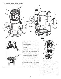
8 - English SWITCHING FROM PLUNGE BASE TO FIXED BASE See Figures 1 - 2, pages 16 - 17. To remove the plunge base: Unplug the router. Loosen the lock lever. Tighten the locking arm for stability. Depress and hold the depth interlock lever. Pull the motor housing until it dislodges from the ...
Page 9 - SELECTING DEPTH OF CUT
9 - English OPERATION SELECTING DEPTH OF CUT Proper depth of cut depends on several factors: the horse-power of the router motor, the type of bit, and the type of wood. A lightweight, low horsepower router is designed for making shallow cuts; a router with higher horsepower is designed for deeper cu...
Page 10 - TURNING THE ROUTER ON AND OFF; VARIABLE SPEED DIAL
10 - English OPERATION Turn the plunge depth stop knob counterclockwise until the scale on the front of the stop reads 1/4 in. Loosen the depth stop bar lock knob and allow the depth stop bar to drop down and contact the top of the plunge depth stop knob. NOTE: If the bar does not drop down, it ...
Page 12 - FEEDING TOO FAST
12 - English OPERATION When cutting shallow grooves in soft woods such as pine, a faster rate of feed can be used. When making cuts in hardwoods such as oak, a slower rate of feed is required.Several factors will help you select the proper rate of feed. Choose the rate that does not slow down the ...
Page 13 - ADJUSTMENTS; ATTACHING/REMOVING VACUUM ADAPTORS
13 - English ADJUSTING LOCK LEVER TENSION ON THE FIXED BASE AND PLUNGE BASE ROUTER See Figure 21, page 19. Over time and with repeated use, the lock lever may become loose. When this occurs, tighten the stop nut slightly. The elastic stop nut should be loose enough so that there is some play in the ...
Page 14 - MAINTENANCE; GENERAL MAINTENANCE
14 - English MAINTENANCE WARNING: Before inspecting, cleaning, or performing any maintenance, make sure the switch is in the OFF (O) position, wait for all moving parts to stop, and disconnect from the power supply. Failure to follow these instructions can result in death, serious personal injury, o...
Page 15 - ACCESSORIES; NOTE: ILLUSTRATIONS START ON PAGE 16
15 - English ACCESSORIES See Figure 24, page 19. Look for these accessories where you purchased this product: Edge Guide Assembly* ........................................................................................................................ Part no. 300869006 Plunge Depth Adjustment...
Page 16 - SÉCURITÉ DU LIEU DE TRAVAIL; SÉCURITÉ ÉLECTRIQUE; RÈGLES DE SÉCURITÉ RELATIVES AUX OUTILS ÉLECTRIQUES
2 - Français AVERTISSEMENT : Lire tous les avertissements et toutes les instructions. Ne pas suivre l’ensemble des avertissements et des instructions peut entraîner une électrocution, un incendie ou des blessures graves. Conserver les avertissements et les instructions à des fins de référence ultéri...
Page 17 - DÉPANNAGE
3 - Français RÈGLES DE SÉCURITÉ RELATIVES AUX OUTILS ÉLECTRIQUES Débrancher l’outil et/ou retirer le bloc-piles avant d’effectuer des réglages, de changer d’accessoire ou de remiser l’outil. Ces mesures de sécurité préventives réduisent les risques de démarrage accidentel de l’outil. Ranger les ...
Page 18 - AVERTISSEMENTS DE SÉCURITÉ RELATIFS AU TOUPIE
4 - Français Tenir l'outil électrique par ses surfaces de préhension isolées étant donné que le fer peut entrer en contact avec le cordon d'alimentation de l'outil. Découpe un fil sous tension « électrifie » les pièces métalliques exposées de l’outil et peut électrocuter l’utilisateur. Dans la m...
Page 19 - SYMBOLES
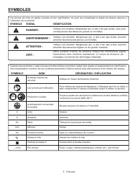
5 - Français Certains des symboles ci-dessous peuvent être utilisés sur produit. Veiller à les étudier et à apprendre leur signification. Une interprétation correcte de ces symboles permettra d’utiliser produit plus efficacement et de réduire les risques. SYMBOLE NOM DÉSIGNATION / EXPLICATION Symbol...
Page 20 - DOUBLE ISOLATION; CONNEXIONS ÉLECTRIQUES; CORDONS PROLONGATEURS; CARACTÉRISTIQUES ÉLECTRIQUES; FICHE TECHNIQUE
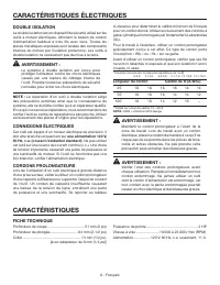
6 - Français DOUBLE ISOLATION La double isolation est un dispositif de sécurité utilisé sur les outils à moteur électriques, éliminant le besoin de cordon d’alimentation habituel à trois fils avec terre. Toutes les pièces métalliques exposées sont isolées des composants internes du moteur par l’isol...
Page 22 - UTILISATION; AVERTISSEMENT
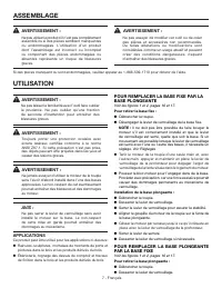
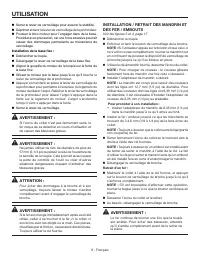
8 - Français UTILISATION INSTALLATION / RETRAIT DES MANDRIN ET DES FER / EMBOUTS Voir les figures 3 et 4, page 17. Débrancher la toupie. Enfoncer et tenir le bouton de verrouillage de la broche. NOTE : Si l’utilisateur appuie sur le bouton et que celui-ci ne s’enfonce pas complètement, tourner l...
Page 23 - RÉGLAGE DE LA PROFONDEUR DE COUPE
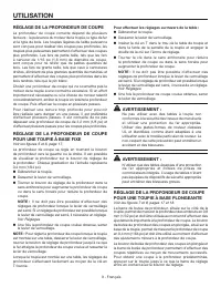
9 - Français RÉGLAGE DE LA PROFONDEUR DE COUPE La profondeur de coupe correcte dépend de plusieurs facteurs : la puissance du moteur de la toupie, le type de fer et le type de bois. Les toupies légères de faible puissance sont conçues pour réaliser des coupes peu profondes, les toupies plus puissant...
Page 24 - MISE EN MARCHE ET ARRÊT DE LA TOUPIE; COMMANDE DE VITESSE VARIABLE
10 - Français UTILISATION Avant de régler la profondeur de coupe désirée, utiliser la barre de butée de profondeur et le bouton de butée de profondeur des coupes en plongée afin d’établir le « point zéro » de la pièce à travailler. NOTE : Le point zéro est généralement constitué par la surface supér...
Page 25 - TOUPILLAGE INTERNE
11 - Français UTILISATION Positionner la règle parallèlement à la ligne de coupe et reporter la distance du bord du fer au bord de la base. Maintenir la base de la toupie contre la règle et pratiquer la rainure.Pour le toupillage d’une rainure plus large que le diamètre du fer, placer une règle de c...
Page 26 - DIRECTION D’ENGAGEMENT; VITESSE D’ENGAGEMENT CORRECTE; AVANCE TROP RAPIDE
12 - Français UTILISATION DIRECTION D’ENGAGEMENT Voir les figures 15 et 16, pages 18 et 19. Le moteur de la toupie et la fraise tournent en sens horaire. Cela donne à l’outil une légère tendance à tourner en sens anti-horaire, en particulier pendant l’accélération du moteur.La toupie doit être engag...
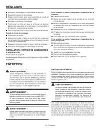
Page 28 - RÉGLAGES; ENTRETIEN GÉNÉRAL
14 - Français Au besoin, désengager le verrouillage de broche. Desserrer le levier de verrouillage. Régler la profondeur pour que l’extrémité de l’outil de centrage et la sous-base soient à égalité. Resserrer le levier de verrouillage. Positionner le cône et l’axe et enfoncer ce dernie...
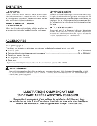
Page 29 - ACCESSOIRES; LUBRIFICATION; ILLUSTRATIONS COMMENÇANT SUR
15 - Français Voir la figure 24, page 19. Pour obtenir ces accessoires, s’adresser au revendeur après duquel vous avez acheté ce produit : Guide de chant* .................................................................................................................................... Réf no...
Page 30 - ÁREA DE TRABAJO; SEGURIDAD ELÉCTRICA; ADVERTENCIAS DE SEGURIDAD PARA HERRAMIENTAS
2 - Español ADVERTENCIA: Lea todas las advertencias de seguridad y las instrucciones. La inobservancia de las advertencias e instrucciones puede causar descargas eléctricas, incendios o lesiones graves. Guarde todas las advertencias e instrucciones para consultarlas en el futuro. El término “herrami...
Page 31 - EMPLEO Y CUIDADO DE LA HERRAMIENTA; SERVICIO
3 - Español ADVERTENCIAS DE SEGURIDAD PARA HERRAMIENTAS ELÉCTRICAS EMPLEO Y CUIDADO DE LA HERRAMIENTA ELÉCTRICA N o f u e rc e l a h e r r a m i e n t a e l é c t r i c a . U t i l i c e l a herramienta eléctrica adecuada para cada trabajo. La herramienta eléctrica adecuada efectúa mejor y de mane...
Page 32 - ADVERTENCIAS DE SEGURIDAD
4 - Español Sostenga la herramienta eléctrica de las superficies de sujeción aisladas, debido a que la fresa puede hacer contacto con su propio cordón. Para cortar una cable cargado cargue las piezas metálicas expuestas de la herramienta eléctrica y dé una descarga eléctrica al operador. Utilice...
Page 33 - SÍMBOLOS
5 - Español Es posible que se empleen en este producto algunos de los siguientes símbolos. Le suplicamos estudiarlos y aprender su significado. Una correcta interpretación de estos símbolos le permitirá utilizar mejor y de manera más segura el producto. SÍMBOLO NOMBRE DENOMINACIÓN/EXPLICACIÓN Alerta...
Page 34 - DOBLE AISLAMIENTO; CONEXIÓN ELÉCTRICA; CORDONES DE EXTENSIÓN; ASPECTOS ELÉCTRICOS; ESPECIFICACIONES DEL PRODUCTO
6 - Español DOBLE AISLAMIENTO El doble aislamiento es una característica de seguridad de las herramientas eléctricas, la cual elimina la necesidad de usar el típico cordón eléctrico de tres conductores con conexión a tierra. Todas las partes metálicas expuestas están aisladas de los componentes metá...
Page 35 - USOS
7 - Español ADVERTENCIA: No use este producto si no está totalmente ensamblado o si alguna pieza falta o está dañada. El uso de un producto que no está adecuadamente y completamente ensamblado o posee partes dañadas o faltantes puede resultar en lesiones personales graves. ADVERTENCIA: No intente mo...
Page 36 - FUNCIONAMIENTO; MONTAJE Y DESMONTAJE DE LOS; ADVERTENCIA
8 - Español FUNCIONAMIENTO MONTAJE Y DESMONTAJE DE LOS PORTAHERRAMIENTAS Y LAS FRESAS Vea las figuras 3 y 4, página 17. Desconecte la fresadora. Oprima y mantenga oprimida la traba del husillo. NOTA: Si el botón está presionado y no se introduce totalmente, gire el portaherramientas mientras con...
Page 38 - SELECTOR DE VELOCIDAD GIRATORIO
10 - Español 90˚ para configuraciones de precisión de 0,40 mm (1/64 pulg.). Al girar la perilla hacia la izquierda sus cortes serán más superficiales y al girar la perilla hacia la derecha, sus cortes serán más profundos. NOTA: Cuente la cantidad de trabas que gira la perilla limitadora de profundid...
Page 39 - FRESADO INTERNO
11 - Español FUNCIONAMIENTO NOTA: También hay a la disponibilidad guías para cantos para la fresadora. Vea el apartado Accesorios . Coloque la regla paralela a la línea de corte, tomando en cuenta la distancia existente entre el filo de corte de la fresa y el borde de la base de la fresadora. Sosten...
Page 40 - AVANCE DEMASIADO RÁPIDO
12 - Español parte, si la guía se coloca como se muestra en la figura 14 (sobresaliendo del canto de la pieza de trabajo), la fresa no efectúa un corte completo, lo cual altera la forma del canto acabado. NOTA: Cualquiera de las fresas de vástago puede usarse sin el vástago para contorneado de canto...
Page 41 - AVANCE DEMASIADO LENTO; AJUSTES; MESA DE ADITAMENTO PARA FRESADORA
13 - Español FUNCIONAMIENTO del sonido del motor. Su zumbido de tono alto sonará más grave y más fuerte al perder velocidad. Además, el esfuerzo para sostener la herramienta aumenta considerablemente. AVANCE DEMASIADO LENTO Vea la figura 18, página 19. Es posible arruinar un corte si se avanza la fr...
Page 42 - MANTENIMIENTO
14 - Español portaherramientas de 6,35 mm (1/4pulg.) debe retirarse antes de que se pueda usar el centrador. Para desmontar la placa de la base de la fresadora: Desconecte la fresadora. Afloje los tornillos de la subbase atornillados en la base. Retire la subbase de la fresadora. Para instal...
Page 43 - ACCESORIOS; MANTENIMIENTO GENERAL
15 - Español Vea la figura 24, página 19. Busque estos accesorios donde adquirió este producto: Conjunto de la guía de cantos* ................................................................................................ Núm. de pieza 300869006 Extensión de la perilla de ajuste de profundidad...
Page 48 - OPERATOR’S MANUAL; Customer Service Information:; Información sobre servicio al consumidor:
995000676 8-28-18 (REV:01) OPERATOR’S MANUAL MANUEL D’UTILISATIONMANUAL DEL OPERADORR29303N ROUTER WITH R2901 MOTOR, R2911 FIXED BASE, AND R29202 PLUNGE BASE R29303N TOUPIE AVEC R2901 MOTEUR, R2911 BASE FIXE ET R29202 BASE PLONGÉER29303N FRESADORA CON R2901 MOTOR, R2911 BASE FIJA Y R29202 BASE TIPO ...