Page 2 - TABLE OF CONTENTS; TABLE DES MATIÈRES / ÍNDICE DE CONTENIDO; INTRODUCTION; INTRODUCTION / INTRODUCCIÓN
2 Introduction ...................................................................................................................................................................... 2 Introduction / Introducción General Safety Rules ................................................................
Page 3 - GENERAL SAFETY RULES; SAVE THESE INSTRUCTIONS
3 - English GENERAL SAFETY RULES WARNING: Read all instructions. Failure to follow all instructions listed below may result in electric shock, fire and/or serious injury. The term “power tool” in all of the warnings listed below refers to your mains-operated (corded) power tool or battery-operated (...
Page 4 - SERVICE
4 - English Hold tool by insulated gripping surfaces when per-forming an operation where the cutting tool may contact hidden wiring or its own cord. Contact with a “live” wire will make exposed metal parts of the cutting tool “live” and shock the operator. Use clamps or another practical way to ...
Page 5 - SYMBOLS
5 - English SYMBOLS Some of the following symbols may be used on this product. Please study them and learn their meaning. Proper inter-pretation of these symbols will allow you to operate the product better and safer. SYMBOL NAME DESIGNATION/EXPLANATION Safety Alert Indicates a potential personal in...
Page 6 - DOUBLE INSULATION; ELECTRICAL CONNECTION; EXTENSION CORDS; ELECTRICAL; PRODUCT SPECIFICATIONS
6 - English DOUBLE INSULATION Double insulation is a concept in safety in electric power tools, which eliminates the need for the usual three-wire grounded power cord. All exposed metal parts are isolated from the internal metal motor components with protect-ing insulation. Double insulated tools do...
Page 8 - OPERATION; WARNING; ASSEMBLY
8 - English WARNING: Do not allow familiarity with this product to make you careless. Remember that a careless fraction of a second is sufficient to inflict serious injury. WARNING: Always wear eye protection with side shields marked to comply with ANSI Z87.1. Failure to do so could result in object...
Page 9 - INSTALLING/REMOVING COLLETS AND BITS; SELECTING DEPTH OF CUT
9 - English WARNING: If you are changing a bit immediately after use, be careful not to touch the collet nut, bit, or collet with your hands or fingers. You will get burned because of the heat build-up from cutting. Always use the wrench provided. INSTALLING/REMOVING COLLETS AND BITS See Figures 4 -...
Page 10 - OPERATING THE ROUTER; INTERNAL ROUTING; TURNING THE ROUTER ON AND OFF; VARIABLE SPEED DIAL
10 - English OPERATING THE ROUTER See Figures 10 - 11, page 17. When routing straight cuts across a workpiece, clamp a straight edge to the workpiece to use as a guide. NOTE: Edge guides for the router are also available. See Accessories . Position the straight edge parallel to the line of cut and o...
Page 11 - FREEHAND ROUTING
11 - English OPERATION WARNING: Do not use large router bits for freehand routing. Use of large router bits when freehand routing could cause loss of control or create other hazardous conditions that could result in personal injury. If using a router table, large bits should be used for edging only....
Page 12 - DEPTH OF CUT
12 - English Notice the chips being produced as you cut. If the router is fed too slowly, it will scorch or burn the wood. If fed too fast, it will take large chips out of the wood and leave gouge marks. Test a cut on a scrap piece of the workpiece before you begin. Always grasp and hold the route...
Page 13 - CENTERING TOOL; ADJUSTMENTS; ROUTER TABLE ATTACHMENT
13 - English ADJUSTING LOCK LEVER TENSION ON THE FIXED BASE ROUTER See Figure 20, page 18. Over time and with repeated use, the lock lever may become loose. When this occurs, tighten the stop nut slightly. The stop nut should be loose enough so that there is some play in the lock lever when it is in...
Page 14 - ACCESSORIES; MAINTENANCE; GENERAL MAINTENANCE; AFTER FRENCH AND SPANISH LANGUAGE SECTIONS.
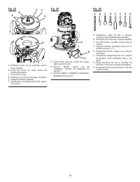
14 - English See Figure 25, page 19. WARNING: Current attachments and accessories available for use with this product are listed above. Do not use any attachments or accessories not recommended by the manufacturer of this product. The use of attachments or accessories not recommended can result in s...
Page 15 - WARRANTY
15 - English WARRANTY Proof of purchase must be presented when requesting warranty service. Limited to RIDGID ® hand held and stationary power tools purchased 2/1/04 and after. This product is manufactured by One World Technologies, Inc. The trademark is licensed from RIDGID, Inc. All warranty commu...
Page 16 - RÈGLES DE SÉCURITÉ GÉNÉRALES; SÉCURITÉ ÉLECTRIQUE
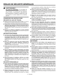
3 - Français RÈGLES DE SÉCURITÉ GÉNÉRALES AVERTISSEMENT : Lire toutes les instructions. Le non-respect de toutes les instructions ci-dessous peut entraîner un choc électrique, un incendie et/ou des blessures graves. Le terme « outil électrique », utlisé dans tous les avertissements ci-dessous, désig...
Page 17 - DÉPANNAGE; RÈGLES DE SÉCURITÉ PARTICULIÈRES
4 - Français RÈGLES DE SÉCURITÉ GÉNÉRALES Lorsque l’outil est utilisé pour un travail risquant de le mettre en contact avec des fils électriques cachés ou son propre cordon d’alimentation, le tenir par les surfaces de prise isolées. En cas de contact avec un fil sous tension, les parties métalliqu...
Page 18 - SYMBOLES
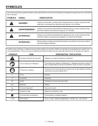
5 - Français SYMBOLES Certains des symboles ci-dessous peuvent être utilisés sur produit. Veiller à les étudier et à apprendre leur signification. Une interprétation correcte de ces symboles permettra d’utiliser produit plus efficacement et de réduire les risques. SYMBOLE NOM DÉSIGNATION / EXPLICATI...
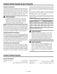
Page 19 - DOUBLE ISOLATION; CONNEXIONS ÉLECTRIQUES; CORDONS PROLONGATEURS; CARACTÉRISTIQUES ÉLECTRIQUES; FICHE TECHNIQUE
6 - Français DOUBLE ISOLATION La double isolation est un dispositif de sécurité utilisé sur les outils à moteur électriques, éliminant le besoin de cordon d’alimentation habituel à trois fils avec terre. Toutes les pièces métalliques exposées sont isolées des composants internes du moteur par l’isol...
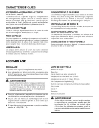
Page 21 - APPLICATIONS; UTILISATION; AVERTISSEMENT; ASSEMBLAGE
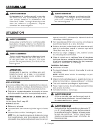
8 - Français AVERTISSEMENT : Ne pas laisser la familiarité avec l’outil faire oublier la prudence. Ne pas oublier qu’une fraction de seconde d’inattention peut entraîner des blessures graves. AVERTISSEMENT : Toujours porter une protection oculaire avec écrans latéraux certifiée conforme à la norme A...
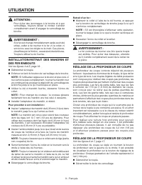
Page 22 - RÉGLAGE DE LA PROFONDEUR DE COUPE
9 - Français ATTENTION : Pour éviter des dommages à la broche et à son verrouillage, toujours laisser le moteur s’arrêter complètement avant d’engager le verrouillage de broche. AVERTISSEMENT : Si le fer est changé immédiatement après avoir été utilisé, veiller à ne toucher ni le fer, ni le collet, ...
Page 23 - MISE EN MARCHE ET ARRÊT DE LA TOUPIE; COMMANDE DE VITESSE VARIABLE
10 - Français UTILISATION Tourner le bouton de réglage de la profondeur dans le sens antihoraire pour augmenter la profondeur de coupe ou dans le sens horaire pour réduire la profondeur de coupe. NOTE : Il ne doit pas être possible d’ajuster la profondeur lorsque le levier de verrouillage est verr...
Page 24 - TOUPILLAGE INTERNE
11 - Français UTILISATION TOUPILLAGE INTERNE Incliner la toupie et la placer sur la pièce sans que le fer touche la pièce. Mettre la toupie en marche et laisser le moteur parvenir à pleine vitesse. Engager le fer dans le matériau progressivement, jusqu’à ce que la semelle repose à plat sur l...
Page 25 - VITESSE D’ENGAGEMENT CORRECTE; AVANCE TROP RAPIDE
12 - Français UTILISATION VITESSE D’ENGAGEMENT CORRECTE Un résultat professionnel est obtenu avec la vitesse d’avance correcte, qui s’acquiert avec l’usage et l’expérience. La vitesse d’engagement à utiliser dépend de plusieurs facteurs : La dureté et la teneur en humidité de la pièce Profondeur...
Page 26 - RÉGLAGES; MONTAGE SUR TABLE À TOUPIE
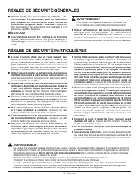
13 - Français RÉGLAGE DE LA TESNION DU LEVIER DE VERROUILLAGE DE BASE FIXES Voir la figure 20, page 18. Après un certain temps et avec un usage répété, le levier de blocage peut se desserrer. Dans ce cas, serrer légèrement l’écrou. L’écrou de blocage élastique doit être assez peu serré pour laisser ...
Page 27 - ACCESSOIRES; ENTRETIEN; ENTRETIEN GÉNÉRAL; FIGURES (ILLUSTRATIONS) COMMENÇANT SUR 16
14 - Français * Disponible exclusivement auprès du service après-vente. Pour toute commande, appeler le 1-866-539-1710. Pour obtenir ces accessoires, s’adresser au revendeur après duquel vous avez acheté ce produit : AVERTISSEMENT : Les outils et accessoires disponibles actuellement pour ce produit...
Page 28 - GARANTIE; RÉPARATIONS SOUS GARANTIE
15 - Français GARANTIE Une preuve d’achat doit être présentée pour toute demande de réparation sous garantie. Cette garantie se limite aux outils électriques à main et d’établi RIDGID ® achetés à partir du 1/2/04. Ce produit est fabriqué par One World Technologies, Inc., sous licence de marque de RI...
Page 29 - REGLAS DE SEGURIDAD GENERALES; GUARDE ESTAS INSTRUCCIONES DE
3 - Español REGLAS DE SEGURIDAD GENERALES ADVERTENCIA: Lea todas las instrucciones. El incumplimiento de las instrucciones señaladas abajo puede causar descargas eléctricas, incendios y lesiones serias. El término “herramienta eléctrica” empleado en todos los avisos de advertencia enumerados abajo s...
Page 30 - SERVICIO; REGLAS DE SEGURIDAD ESPECÍFICAS
4 - Español REGLAS DE SEGURIDAD GENERALES Sujete la herramienta eléctrica por las superficies aisladas de sujeción al efectuar una operación en la cual la herramienta de corte pueda entrar en contacto con cables ocultos o con su propio cordón eléctrico. Con cualquier contacto de una herramienta de...
Page 31 - SÍMBOLOS
5 - Español SÍMBOLOS Las siguientes palabras de señalización y sus significados tienen el objeto de explicar los niveles de riesgo relacionados con este producto. SÍMBOLO SEÑAL SIGNIFICADO PELIGRO: Indica una situación peligrosa inminente, la cual, si no se evita, causará la muerte o lesiones serias...
Page 32 - DOBLE AISLAMIENTO; CONEXIÓN ELÉCTRICA; CORDONES DE EXTENSIÓN; ASPECTOS ELÉCTRICOS; ESPECIFICACIONES DEL PRODUCTO
6 - Español DOBLE AISLAMIENTO El doble aislamiento es una característica de seguridad de las herramientas eléctricas, la cual elimina la necesidad de usar el típico cordón eléctrico de tres conductores con conexión a tierra. Todas las partes metálicas expuestas están aisladas de los componentes metá...
Page 33 - CARACTERÍSTICAS; LUCES DE TRABAJO DE DIODO; ARMADO
7 - Español CARACTERÍSTICAS FAMILIARÍCESE CON LA FRESADORA Vea la figura 1, página 16. Para usar este producto con la debida seguridad se debe comprender la información indicada en la herramienta misma y en este manual, y se debe comprender también el trabajo que intenta realizar. Antes de usar este...
Page 34 - FUNCIONAMIENTO; ADVERTENCIA
8 - Español ADVERTENCIA: No permita que su familarización con las herramientas lo vuelva descuidado. Tenga presente que un descuido de un instante es suficiente para infligir una lesión grave. ADVERTENCIA: Siempre póngase protección ocular con protección lateral con la marca de cumplimiento de la no...
Page 35 - AJUSTE DE LA PROFUNDIDAD DE CORTE
9 - Español PRECAUCIÓN: Para evitar dañar el husillo o el seguro del mismo, siempre deje que el motor se detenga completamente antes de enganchar el seguro. ADVERTENCIA: Si se dispone a cambiar una fresa inmediatamente después de usarla, tenga cuidado de no tocar la tuerca del portaherramientas, la ...
Page 36 - FRESADO INTERNO
10 - Español SELECTOR DE VELOCIDAD GIRATORIO Vea la figura 9, página 17. La fresadora dispone de un selector de velocidad diseñado para permitir al operador controlar y ajustar los límites de velocidad y potencia. La velocidad y la potencia de la fresadora pueden aumentarse o disminuirse girando el ...
Page 37 - FRESADO DE CANTOS; FRESADO A PULSO; FRESADO DE CANTOS CON FRESAS DE
11 - Español FUNCIONAMIENTO FRESADO DE CANTOS Sujete una regla (pieza recta) a la pieza de trabajo mediante prensas de mano, a manera de guía. Coloque la fresadora en el canto de la pieza de trabajo sin que la fresa la toque. Encienda la fresadora y deje que el motor alcance plena velocidad....
Page 38 - AVANCE DEMASIADO RÁPIDO; AVANCE DEMASIADO LENTO
12 - Español Hay varios factores que le ayudarán a seleccionar la velocidad de avance correcta. Escoja una velocidad de avance que no aminore la velocidad de giro del motor. Escoja una velocidad de avance a la cual la fresa avance firme y seguramente para producir una espiral continua de viruta...
Page 39 - CENTRADOR; AJUSTES; MESA DE ADITAMENTO PARA FRESADORA
13 - Español AJUSTE DE LA TENSIÓN DE LA PALANCA DE FIJACIÓN DE LA FRESADORA CON BASE FIJA Vea la figura 20, página 18. Al paso del tiempo y con el uso repetido, puede aflojarse la palanca de fijación. Cuando ocurra tal cosa, apriete levemente la tuerca tope. La tuerca tope elástica debe quedar con l...
Page 40 - ACCESORIOS; MANTENIMIENTO GENERAL
14 - Español Conjunto de la guía de cantos*............................Núm. de pieza 300869006 Juego de plantilla para ensambladura de cola de milano Busque estos accesorios donde adquirió este producto: ADVERTENCIA: Arriba se señalan los aditamentos y accesorios disponibles para usarse con ...
Page 41 - GARANTÍA; LO QUE ESTÁ CUBIERTO POR LA GARANTÍA; LIMITACIONES ADICIONALES
15 - Español GARANTÍA Debe presentarse prueba de la compra al solicitar servicio al amparo de la garantía. Se limita a las herramientas de mano y estacionarias RIDGID ® adquiridas a partir de 1/feb./04. Este producto está manufacturado por One World Technologies, Inc., La licencia de uso de la marca...
Page 48 - Customer Service Information:; Información sobre servicio al consumidor:; OPERATOR’S MANUAL
988000-474 1-28-11 (REV:01) Customer Service Information: For parts or service, contact your nearest RIDGID ® authorized service center. Be sure to provide all relevant information when you call or visit. For the location of the authorized service center nearest you, please call 1-866-539-1710 or vi...