Page 2 - Registered trademark of Rheem Australia Pty Ltd.; with the householder or a responsible officer.; DO NOT; leave this guide inside of the cover of the water
PATENTS This water heater may be protected by one or more patents or registered designs in the name of Rheem Australia Pty Ltd or Paloma Co., Ltd. Rheem Australia Pty Ltd is the supplier of the Rheem range of continuous flow gas water heaters, manufactured by Paloma Co., Ltd., a world leader in wate...
Page 3 - CONTENTS
3 CONTENTS HOUSEHOLDER - We recommend you read pages 4 to 43. The other pages are intended for the installer but may be of interest. About Your Water Heater ............................................................................................................ 4 Temperature Control ...............
Page 4 - ABOUT YOUR WATER HEATER; WATER HEATER APPLICATION; must not; MAINS PRESSURE
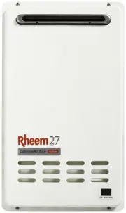
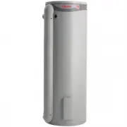
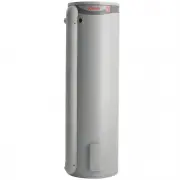
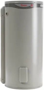
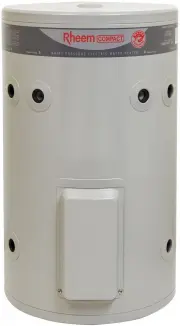
4 ABOUT YOUR WATER HEATER WATER HEATER APPLICATION This water heater is designed for use in a single family domestic dwelling for the purpose of heating potable water. Its use in an application other than this may shorten its life. MODEL TYPE The Rheem ® continuous flow gas water heater model you ha...
Page 5 - GAS BOOSTING FOR A SOLAR WATER HEATER; be fitted to this water heater (874 series) if it is installed as; must be; HOTTER WATER INCREASES THE RISK OF SCALD INJURY
ABOUT YOUR WATER HEATER 5 GAS BOOSTING FOR A SOLAR WATER HEATER Water stored in the solar storage tank passes through the in-series gas booster when a hot tap is opened. The in-series gas booster is for heating water at times of low solar energy gain, such as during cloudy or rainy weather, or durin...
Page 6 - WARNING; flammable or combustible materials; PRECAUTIONS
ABOUT YOUR WATER HEATER 6 WARNING This water heater is only intended to be operated by persons who have the experience or the knowledge and the capabilities to do so. This water heater is not intended to be operated by persons with reduced physical, sensory or mental capabilities i.e. the infirm, or...
Page 7 - GENERAL MAINTENANCE; Warning; Check and if necessary adjust the gas pressure.
ABOUT YOUR WATER HEATER 7 GENERAL MAINTENANCE The jacket of the water heater can be cleaned with a soft cloth and warm mild soapy water. Under no circumstances should abrasive materials or powders be used. The area around the water heater can be sprayed with insecticide to rid the area of insects. I...
Page 8 - TO TURN OFF THE WATER HEATER
ABOUT YOUR WATER HEATER 8 TO TURN OFF THE WATER HEATER If it is necessary to turn off the water heater: Turn off the controller(s) (if fitted) by pressing the on / off button. The light in the on / off button will go out and the priority light (standard controller) or the ACTIVE light (Deluxe contro...
Page 9 - DRAINING THE WATER HEATER; VICTORIAN CUSTOMERS
ABOUT YOUR WATER HEATER 9 DRAINING THE WATER HEATER Turn off the water heater (refer to “Turn Off The Water Heater” on page 8). Open a hot tap (preferably the shower outlet). Unscrew the two drain plugs, one each at the cold water inlet and hot water outlet, on the underside of the water heater. Wat...
Page 10 - TEMPERATURE CONTROL; CONTROLLERS; Standard Controllers; “Bath Fill Mode”
10 TEMPERATURE CONTROL CONTROLLERS The Rheem 874 and 876 series can be installed with Rheem controllers to enable the user to control the temperature of the delivered water from the outlet of the water heater. There are two families of Rheem controllers suitable for installation with this water heat...
Page 11 - TEMPERATURE CONTROL – STANDARD; STANDARD CONTROLLER FUNCTIONS
11 TEMPERATURE CONTROL – STANDARD STANDARD CONTROLLER FUNCTIONS If one or more controllers are installed, at least one must be on for the water heater to operate. If all controllers are off, the water heater will only deliver cold water. on / off button – This button must be pressed once to turn on ...
Page 12 - STANDARD CONTROLLER; operating light and; water volume; symbol are on the Kitchen
TEMPERATURE CONTROL – STANDARD 12 STANDARD CONTROLLER Note: water volume button, water volume operating light and water volume symbol are on the Kitchen controller only. SILENCING A CONTROLLER – STANDARD The controller emits a sound whenever a button is pressed. This sound can be turned off to provi...
Page 13 - TEMPERATURE SETTINGS
TEMPERATURE CONTROL – STANDARD 13 TEMPERATURE SETTINGS – STANDARD CONTROLLER The temperature settings of each type of controller are: Bathroom1 & 2 37°C to 48°C (in 1°C increments), 50°C Kitchen 37°C to 48°C (in 1°C increments), 50°C*, 55°C, 60°C * limited to 50°C on an 876 series model. Tempera...
Page 14 - TEMPERATURE ADJUSTMENT
TEMPERATURE CONTROL – STANDARD 14 TEMPERATURE ADJUSTMENT – STANDARD CONTROLLER A controller must be on and have priority to be able to adjust the temperature setting. The temperature adjustment is made by pressing the up ( ) button or down ( ) button. The maximum temperature setting for the cont...
Page 15 - KITCHEN CONTROLLER; Notes on the Kitchen controller:; The controller cannot be turned on whilst a hot tap is open.
TEMPERATURE CONTROL – STANDARD 15 KITCHEN CONTROLLER – STANDARD The Kitchen controller allows the user to select the temperature setting for the hot water to be used in the kitchen and laundry. It has a minimum temperature setting of 37°C and a maximum temperature setting of: 874 series 60°C 876 ser...
Page 16 - Refer to the; Turn on the Kitchen controller; Refer to; Turn off the Kitchen controller; Turn off the Kitchen controller after hot water usage; Important
TEMPERATURE CONTROL – STANDARD 16 To operate the Kitchen controller: 1. Turn off the Bathroom controller(s) If a temperature setting is displayed and the priority light is not glowing, it is necessary to turn off the Bathroom controller(s) to gain priority. Refer to the notes on the Kitchen cont...
Page 17 - BATHROOM CONTROLLERS; Notes on the Bathroom controllers:; bathroom; Bathroom Controller
TEMPERATURE CONTROL – STANDARD 17 BATHROOM CONTROLLERS – STANDARD The Bathroom controller(s) allows the user to select the temperature setting for the hot water to be used in the bathroom. They have a minimum temperature setting of 37°C and a maximum temperature setting of: 874 series 50°C 876 serie...
Page 18 - Turn on the Bathroom controller; Open the hot tap; The in use light will glow on all controllers.; Close the hot tap; warning; in the notes on page 17.
TEMPERATURE CONTROL – STANDARD 18 c h e c k h o t w a t e r t e m p e r a t u r e b e f o r e u s e o n o f f 40 C p r i o r i t y i n u s e 42 C p r i o r i t y i n u s e 42 C p r i o r i t y i n u s e 42 C p r i o r i t y i n u s e To operate a Bathroom controller: 1. Turn off the Kitchen controll...
Page 19 - WATER VOLUME FUNCTION; It does not stop either the flow of or the heating of water.; notes on the water volume; Turn on the water volume alarm
TEMPERATURE CONTROL – STANDARD 19 WATER VOLUME FUNCTION – STANDARD CONTROLLER The water volume function is designed to warn, by a beeping sound, that a certain volume of water has been delivered from the water heater. It does not stop either the flow of or the heating of water. This function is part...
Page 20 - Turn off the alarm; “Silencing A
TEMPERATURE CONTROL – STANDARD 20 5. Turn off the alarm Press the water volume button to turn off the alarm. The water volume operating light goes out and 0 x10 l is displayed momentarily on the controller. The temperature setting of the controller with priority is then displayed. 6. Close the hot...
Page 21 - TEMPERATURE CONTROL – DELUXE; DELUXE CONTROLLER FUNCTIONS
21 TEMPERATURE CONTROL – DELUXE DELUXE CONTROLLER FUNCTIONS If one or more Deluxe controllers are installed, at least one must be on or the bath fill function activated for the water heater to operate. If all Deluxe controllers and the bath fill function are off, the water heater will only deliver c...
Page 22 - DELUXE CONTROLLER; Rheem; BATH
TEMPERATURE CONTROL – DELUXE 22 bath fill water volume display panel – The selected bath fill water volume is displayed in litres on all Deluxe controllers. The selected bath fill water volume is displayed whenever the Bath Fill mode is on (refer to “Bath Fill Mode” on page 31) or when the bath fill...
Page 23 - VOICE PROMPT AND OPERATING TONE; Voice Prompt
TEMPERATURE CONTROL – DELUXE 23 VOICE PROMPT AND OPERATING TONE The Deluxe controllers have a series of voice prompts and operating tones which sound during certain operations. The voice prompts and operating tones sound from all Deluxe controllers, regardless of which Deluxe controller is being ope...
Page 24 - Adjusting the Volume of the Voice Prompt and Operating Tone; Turn off all Deluxe controllers.; To Call for Assistance; The voice prompt will sound on all Deluxe controllers,; “assistance required,
TEMPERATURE CONTROL – DELUXE 24 Adjusting the Volume of the Voice Prompt and Operating Tone The volume of the voice prompt and the operating tone can be adjusted to a level comfortable for you. The volume of the voice prompt and the operating tone can be adjusted independently of each other. The vol...
Page 25 - Temperature settings; Refer to
TEMPERATURE CONTROL – DELUXE 25 TEMPERATURE SETTINGS – DELUXE CONTROLLERS The temperature settings of each type of Deluxe controller are: Bathroom1 & 2 Deluxe 37°C to 48°C* (in 1°C increments), 50°C Kitchen Deluxe 37°C to 48°C* (in 1°C increments), 50°C**, 55°C, 60°C * limited to 48°C when set t...
Page 26 - up
TEMPERATURE CONTROL – DELUXE 26 TEMPERATURE ADJUSTMENT – DELUXE CONTROLLERS A controller must be on with the ACTIVE indicator displayed to be able to adjust the temperature setting. The temperature adjustment is made by pressing the up ( ) button or down ( ) button. The minimum temperature setti...
Page 27 - Notes on the Kitchen Deluxe controller:; The Deluxe controller cannot be turned on whilst a hot tap is open.; Kitchen Deluxe Controller
TEMPERATURE CONTROL – DELUXE 27 KITCHEN CONTROLLER – DELUXE The Kitchen Deluxe controller allows the user to select the temperature setting for the hot water to be used in the kitchen and laundry. It has a minimum temperature setting of 37°C and a maximum temperature setting of: 874 series 60°C 876 ...
Page 28 - Turn off the Bathroom Deluxe controller(s); Refer to the notes on the; Turn on the Kitchen Deluxe controller; “hot water temperature has been increased”; Turn off the Kitchen Deluxe controller; note for Bathroom Deluxe controllers on page 29.
TEMPERATURE CONTROL – DELUXE 28 To operate the Kitchen Deluxe controller: 1. Turn off the Bathroom Deluxe controller(s) If a temperature setting is displayed and the ACTIVE light is not glowing, it is necessary to turn off the Bathroom Deluxe controller(s) to gain priority. Refer to the notes on...
Page 29 - Notes on the Bathroom Deluxe controllers:; Bathroom Deluxe controller in the other bathroom.; The Kitchen Deluxe controller will gain priority; Bathroom Deluxe; front cover
TEMPERATURE CONTROL – DELUXE 29 BATHROOM CONTROLLERS – DELUXE The Bathroom Deluxe controller(s) allows the user to select the temperature setting for the hot water to be used in the bathroom. They have a minimum temperature setting of 37°C and a maximum temperature setting of: 874 series 50°C 876 se...
Page 30 - Bathroom Deluxe; Turn on the Bathroom Deluxe controller
TEMPERATURE CONTROL – DELUXE 30 To operate a Bathroom Deluxe controller: 1. Turn off the Kitchen Deluxe controller If a temperature setting is displayed and the ACTIVE and ON / OFF operating lights are not glowing, it is advised to turn off the Kitchen Deluxe controller. Refer to the notes on the ...
Page 31 - BATH FILL MODE
TEMPERATURE CONTROL – DELUXE 31 BATH FILL MODE The Bath Fill mode is designed to allow the water heater to deliver a selected volume of water at a selected temperature. The Bath Fill mode commences when the BATH FILL button is on and a hot tap is opened. When the set volume has been delivered, the w...
Page 32 - Close the front panel on the Deluxe controller.; “please ensure the bath hot water tap is turned off”
TEMPERATURE CONTROL – DELUXE 32 5. Close the front panel on the Deluxe controller. 6. Turn on the Bath Fill mode Press the BATH FILL button. On all Deluxe controllers: The BATH FILL operating light will glow. The bath fill temperature setting will appear on the temperature display panel. The...
Page 34 - “bath fill water volume has been decreased”
TEMPERATURE CONTROL – DELUXE 34 4. Set the bath fill water volume Press the BATH FILL VOLUME ( up button) or the BATH FILL VOLUME ( down button). The first press of either the BATH FILL VOLUME ( up button) or the BATH FILL VOLUME ( down button) will display the last selected bath fill wate...
Page 35 - Turn off the Bath Fill mode
TEMPERATURE CONTROL – DELUXE 35 7. Open the hot tap. The operating light will glow on all Deluxe controllers. Measurement of the water flow at the water heater will commence when the hot tap is opened. Notes: If a second hot tap is opened when the Bath Fill mode is turned on, the set bath fill wat...
Page 36 - Turning Off Bath Fill Mode During Its Operation; Step
TEMPERATURE CONTROL – DELUXE 36 Turning Off Bath Fill Mode During Its Operation The bath fill operation can be interrupted by pressing the BATH FILL button before completion of the bath fill operation. If it is necessary to turn off the Bath Fill mode before the operation is complete, during Step 7:...
Page 37 - Notes on the Bath Fill mode:; “please ensure the bath hot water tap is turned off”.
TEMPERATURE CONTROL – DELUXE 37 Notes on the Bath Fill mode: The Bath Fill mode can be set, turned on and turned off at any of the Deluxe controllers. The Deluxe controllers do not require to have priority (ACTIVE light glowing) or be on in order to set the bath fill water volume or bath fill temper...
Page 38 - Opening a Second Hot Water Tap During Bath Fill Operation; “Turning Off Bath Fill Mode During Its Operation”
TEMPERATURE CONTROL – DELUXE 38 Opening a Second Hot Water Tap During Bath Fill Operation The bath fill water volume is measured as the water flows through the water heater. If more than one hot tap is open, the Bath Fill mode will measure the total water volume drawn from all taps and the expected ...
Page 39 - During; “hot water temperature has been decreased”; During
TEMPERATURE CONTROL – DELUXE 39 Operation of the Bath Fill mode whilst a Deluxe Controller is ACTIVE It is recommended the Bath Fill mode be set and operated with the Deluxe controllers turned off (refer to Step 1 on page 33). However, if a Deluxe controller is ACTIVE during the setting and operatio...
Page 40 - WATER SUPPLIES; CHANGE OF WATER SUPPLY; GAS CONTINUOUS FLOW WATER HEATERS; WITHIN WARRANTY
40 WATER SUPPLIES This water heater must be installed in accordance with this advice to be covered by the Rheem warranty. This water heater is manufactured to suit the water conditions of most public reticulated water supplies. However, there are some known water chemistries which can have detriment...
Page 41 - SAVE A SERVICE CALL; “Terms of the Rheem Warranty”
41 SAVE A SERVICE CALL Check the items below before making a service call. You will be charged for attending to any condition or fault, which is not related to manufacture or failure of a part (refer to “Terms of the Rheem Warranty” on page 79). NO DISPLAY ON THE CONTROLLER Is the controller turned ...
Page 42 - WATER FLOW FLUCTUATES
SAVE A SERVICE CALL 42 WATER FLOW FLUCTUATES More than two or three taps in use at the same time may cause a decrease in the hot water flow from the taps. This can also be evident if the water heater has been installed as an in-series gas booster to a solar water heater and the solar heated water is...
Page 43 - CLOUDS OF WHITE ‘VAPOUR’ FROM THE FLUE TERMINAL; Normal operation; “Mains Water Supply”
SAVE A SERVICE CALL 43 CLOUDS OF WHITE ‘VAPOUR’ FROM THE FLUE TERMINAL During the heating cycle, it is not unusual to see water vapour clouds steaming from the flue terminal, particularly on cold days. This is normal operation of the water heater. PRESSURE RELIEF VALVE DISCHARGING A pressure relief ...
Page 44 - INSTALLATION – WATER HEATER; INSTALLATION STANDARDS; WATER HEATER LOCATION
44 INSTALLATION – WATER HEATER THIS WATER HEATER IS FOR OUTDOOR INSTALLATION ONLY. THIS WATER HEATER IS NOT SUITABLE FOR POOL HEATING. Check the water heater is suitable for the gas type available. (refer to the rating label on the water heater) INSTALLATION STANDARDS The water heater must be instal...
Page 45 - The water heater must be well secured to the wall or; Clearance Requirements
INSTALLATION – WATER HEATER 45 This water heater must be installed vertically upright with the water, gas and power connections on the underside, pointing toward the ground. The back of the water heater can be either against a wall or supported by a frame. Note: The water heater must be well secured...
Page 46 - PIPE COVER; Relief valve setting; some models. Refer to the Owner‟s Guide and Installation
INSTALLATION – WATER HEATER 46 PIPE COVER The pipe work to the water heater can be housed within a pipe cover. A pipe cover kit (PN 299830) is available for such an installation. Refer to the installation instructions which accompany the pipe cover kit. RECESS INSTALLATION The water heater can be in...
Page 47 - HOT WATER DELIVERY; Two Temperature Zones Using a Temperature Limiting Device; Gas Booster for a Solar Water Heater
INSTALLATION – WATER HEATER 47 HOT WATER DELIVERY This water heater can deliver water at temperatures which can cause scalding. It is necessary and we recommend that a temperature limiting device be fitted between an 874 series water heater and the hot water outlets in any ablution and public areas ...
Page 48 - before the non return valve prior; MUST BE; installed on the cold water line to the solar storage tank; AFTER
INSTALLATION – WATER HEATER 48 Where a temperature limiting device is installed adjacent to the in-series gas booster, the cold water line to the temperature limiting device can be branched off the cold water line either before or after the isolation valve and pressure limiting valve to the solar st...
Page 49 - CIRCULATED HOT WATER FLOW AND RETURN SYSTEM; A Rheem 876 series continuous flow water heater; be installed as part of a circulated; Temperature Limiting Device
INSTALLATION – WATER HEATER 49 CIRCULATED HOT WATER FLOW AND RETURN SYSTEM A Rheem 874 627 model continuous flow water heater can be installed as part of a circulated hot water flow and return system in a building. Notes: the preset outlet temperature setting of the water heater must be set to at le...
Page 50 - Circulated Hot Water Flow and Return
INSTALLATION – WATER HEATER 50 LEGEND LEGEND Circulated Hot Water Flow and Return Continuous Flow Gas Water Heater LEGEND LEGEND Circulated Hot Water Flow and Return In-series Gas Booster as part of a Solar Water Heater Installation REDUCING HEAT LOSSES The hot water line from the water heater and t...
Page 51 - WATER TEMPERATURE DIAGRAMS
INSTALLATION – WATER HEATER 51 WATER TEMPERATURE DIAGRAMS 874 Series - Kitchen and Bathroom Controllers 876 Series – Kitchen and Bathroom Controllers 874 Series - Kitchen Controller Only 876 Series - Kitchen Controller Only 874 Series - Bathroom Controllers Only 876 Series - Bathroom Controllers Onl...
Page 53 - DIMENSIONS
INSTALLATION – WATER HEATER 53 DIMENSIONS – STANDARD CONTROLLERS Kitchen Controller (Standard) Bathroom Controller (Standard)
Page 54 - Deluxe Controller – Cover Closed; Deluxe Controllers - Dimension Drawings; Deluxe Controller – Cover Open
INSTALLATION – WATER HEATER 54 DIMENSIONS – DELUXE CONTROLLERS U U P Set Bath Fill Water Volume and Temperature Bath Water Volume BathFillTemp Bath Fill 1. 2. 3. 5. 7. Press Bath Fill Button (Red light on) 4. Open hot tap Bath Fill completed (automatic) Bath Fill Button (Red light flashes) 6. Close ...
Page 55 - TYPICAL INSTALLATION
INSTALLATION – WATER HEATER 55 TYPICAL INSTALLATION – OUTDOOR LOCATION TYPICAL INSTALLATION ELECTRONIC CONTINUOUS FLOW GAS WATER HEATER EXTERNAL MODELS 872,874,876 SERIES
Page 56 - CONNECTIONS – PLUMBING; CONNECTION SIZES; Model; WATER INLET AND OUTLET; A non return valve or stop tap must not be; “Hot Water Delivery”; WATER AND GAS CONNECTION DETAIL; Gas Water Heater
56 CONNECTIONS – PLUMBING All plumbing work must be carried out by a qualified person and in compliance with the Standard AS/NZS 3500.4 and all local codes and regulatory authority requirements. All gas work must be carried out by a qualified person and in compliance with the Standard AS 5601 or AS/...
Page 57 - PIPE SIZES; of copper and be fully insulated with a closed cell type; CONNECTIONS – ELECTRICAL; Temperature controllers; Component; Gas water heater
CONNECTIONS – PLUMBING 57 PIPE SIZES The pipe sizing for hot water supply systems should be carried out by persons competent to do so, choosing the most suitable pipe size to ensure adequate flow for each individual application. Reference to the technical specifications of the water heater and local...
Page 58 - EZ-LINK SYSTEM DUAL INSTALLATION; be fitted to a water heater as part of a solar
58 EZ-LINK SYSTEM DUAL INSTALLATION The EZ- Link™ system is designed to electronically control two continuous flow gas water heaters and have them operate as one. One or both water heaters may be in operation, depending upon the hot water demand. The second water heater will only operate when the ho...
Page 59 - DUAL INSTALLATION; Label Positioning
EZ-LINK SYSTEM DUAL INSTALLATION 59 DUAL INSTALLATION The two continuous flow water heaters can be installed side by side with minimal clearance between them. The AGA has approved the installation of two of this model water heater with an exemption from the 300 mm minimum clearance requirements betw...
Page 60 - EZ-LINK CABLE CONNECTION; dip switch settings; dip switch settings
EZ-LINK SYSTEM DUAL INSTALLATION 60 EZ-LINK CABLE CONNECTION The references in steps 5 to 8 are to the „Control Board with Ez-Link Connection‟ diagram on page 61. To connect the Ez-Link cable to the water heaters: Refer to “Installation – Controllers” on page 63 for information on the installation o...
Page 61 - Increase the hot water flow by turning on an additional hot tap(s).; Control Board with Ez-Link Connection
EZ-LINK SYSTEM DUAL INSTALLATION 61 11. Switch on the electrical supply at the power outlet to the water heater. 12. Turn on the controller by pressing the on / off button, if one is installed. The light in the on / off button and the priority light (standard controller) or ACTIVE light (Deluxe cont...
Page 62 - MANIFOLD INSTALLATION - EZ LINK CONNECTION; Typical Two Unit Manifold with Ez-Link Connection
EZ-LINK SYSTEM DUAL INSTALLATION 62 MANIFOLD INSTALLATION - EZ LINK CONNECTION TWO CONTINUOUS FLOW WATER HEATERS - 872,874,876 SERIES 027 & 627 MODELS 350 eaves, balconies& other projections 300 MIN no minimum distance requirement to return wall 300 Min.openings into building 500 Min. COLD W...
Page 63 - INSTALLATION – CONTROLLERS; disconnected and removed.
63 INSTALLATION – CONTROLLERS CONTROLLERS The Rheem 874 and 876 series can be installed with Rheem controllers to enable the user to control the temperature of the delivered water from the outlet of the water heater. There are two families of Rheem controllers suitable for installation with this wat...
Page 64 - Location; Outdoors. The controllers are not weatherproof.; Kitchen Deluxe Controller Components
INSTALLATION – CONTROLLERS 64 Location – The controllers must be installed in dry, shaded and clean locations. Do not install the controllers: Near a heat source, such as a cook top, stove or oven. Heat, steam and smoke will interfere with the electronic components of the controllers. In direct sunl...
Page 65 - Wiring installation:; “Connecting the Controller(s) to the Water Heater”
INSTALLATION – CONTROLLERS 65 Wiring installation: 1. Penetrate the wall with a 30-35 mm hole at the controller location. 2. Install the Kitchen controller cable between the location of the controller and the water heater. 3. Remove the base plate from the controller. 4. Draw the cable through the c...
Page 66 - Kitchen Controller (Standard and Deluxe) Installation
INSTALLATION – CONTROLLERS 66 If it is necessary to have an exposed wiring installation, follow this procedure omitting Steps 1 and 4, and make an opening in the thin section in the underside of the controller to accommodate the cable (as shown in the diagram), prior to Step 6. Kitchen Controller (S...
Page 67 - BATHROOM1 AND BATHROOM2 CONTROLLERS; Bathroom Deluxe Controller Components; Bathroom1 Deluxe and Bathroom2 Deluxe Controller Components
INSTALLATION – CONTROLLERS 67 BATHROOM1 AND BATHROOM2 CONTROLLERS If only one Bathroom controller is to be installed, the standard Bathroom1 Controller (Rheem PN 299854) or the Bathroom1 Deluxe controller (Rheem PN 299862) must be used. If two Bathroom controllers are to be installed, one must be a ...
Page 69 - CONNECTING THE CONTROLLER(S) TO THE WATER HEATER
INSTALLATION – CONTROLLERS 69 CONNECTING THE CONTROLLER(S) TO THE WATER HEATER To connect the controller(s) to the water heater: 1. Ensure the electrical supply to the water heater is switched off. 2. Unscrew and gently remove the electrical cover from the underside of the water heater. 3. Draw the ...
Page 70 - COMMISSIONING; TO TURN ON THE WATER HEATER; GAS INLET PRESSURE
70 COMMISSIONING All water heaters are tested and adjusted before dispatch from the factory, however further adjustments may become necessary because of local conditions. TO TURN ON THE WATER HEATER Open all of the hot taps in the house (don‟t forget the shower). Open the cold water isolation valve ...
Page 71 - Gas Inlet Test Point Pressure
COMMISSIONING 71 Gas Inlet Test Point Pressure To check the gas inlet pressure: 1. Close any hot taps and ensure the burners are not operating. 2. Close the gas isolation valve at the gas inlet to the water heater. 3. Locate the gas inlet test point on the gas connection to the water heater. Remov...
Page 72 - BURNER GAS PRESSURE; Minimum test point gas pressure; DIP SWITCH AND ADJUSTMENT BUTTONS; LED DISPLAY - TEST POINT GAS PRESSURE
COMMISSIONING 72 BURNER GAS PRESSURE It is necessary to check the burner gas pressure at both the minimum and maximum operational settings. To check and if necessary adjust the operational gas pressures, the electrical supply to the water heater must be switched on, the burners ignited and hot water...
Page 73 - “Clearing Error Code”; Maximum test point gas pressure; “Minimum test point gas pressure”; Clearing Error Code
COMMISSIONING 73 Notes: If the burners extinguish and error code 11 or 12 starts to flash on the LED display: release the MIN and adjuster buttons close the hot tap clear the error code (refer to “Clearing Error Code” on page 73) recommence the procedure from Step 8. If the adjuster button i...
Page 74 - PRESET OUTLET TEMPERATURE SETTING
COMMISSIONING 74 PRESET OUTLET TEMPERATURE SETTING The factory preset outlet temperature setting of the water heater is: 874 series 60°C 876 series 50°C If a temperature controller is connected to the water heater, this will override the preset outlet temperature setting and the maximum temperature ...
Page 75 - TO CHECK OR ADJUST THE PRESET OUTLET TEMPERATURE SETTING; OFF; LED Display; OFF ON; OFF ON; OFF ON
COMMISSIONING 75 TO CHECK OR ADJUST THE PRESET OUTLET TEMPERATURE SETTING The temperature settings will be displayed on the LED display. The preset outlet temperature settings are: 874 series 38°C, 40°C, 42°C, 43°C, 45°C, 50°C, 55°C, 60°C, 70°C, 75°C 876 series 38°C, 40°C, 42°C, 43°C, 45°C, 50°C It ...
Page 76 - OUTLET TEMPERATURE COMPENSATION ADJUSTMENT; Warnings; “To Check or Adjust the Preset; Outlet Temperature Adjustment
COMMISSIONING 76 OUTLET TEMPERATURE COMPENSATION ADJUSTMENT – 876 SERIES The maximum outlet temperature of an 876 series water heater may be adjusted to compensate for temperature losses in the pipe work between the water heater outlet and sanitary fixtures. Warnings After adjustment the water tempe...
Page 78 - Turn off the water heater (refer to
COMMISSIONING 78 TO TURN OFF THE WATER HEATER If it is necessary to turn off the water heater on completion of the installation, such as on a building site or where the premises is vacant, then: Turn off the controllers(s) (if fitted) by pressing the on / off button. The light in the on / off button...
Page 79 - CONTINUOUS FLOW GAS WATER HEATERS 874, 876 SERIES 627 MODELS; TERMS OF THE RHEEM WARRANTY AND EXCLUSIONS TO IT; s at Rheem’s sole discretion.
79 RHEEM CONTINUOUS FLOW GAS WATER HEATER WARRANTY – AUSTRALIA ONLY CONTINUOUS FLOW GAS WATER HEATERS 874, 876 SERIES 627 MODELS 1. THE RHEEM WARRANTY – GENERAL 1.1 This warranty is given by Rheem Australia Pty Limited ABN 21 098 823 511 of 1 Alan Street, Rydalmere New South Wales, the supplier of R...
Page 80 - Australian Consumer Law
RHEEM CONTINUOUS FLOW GAS WATER HEATER WARRANTY – AUSTRALIA ONLY Revision Date: 2013 July 122202C 80 CONTINUOUS FLOW GAS WATER HEATERS 874, 876 SERIES 627 MODELS 3. WHAT IS COVERED BY THE RHEEM WARRANTY FOR THE WATER HEATERS DETAILED IN THIS DOCUMENT 3.1 Rheem will repair or replace a faulty compone...


 Rheem 111160
User Manual
Rheem 111160
User Manual
 Rheem 191050
User Manual
Rheem 191050
User Manual
 Rheem 491250
User Manual
Rheem 491250
User Manual
 Rheem 111025G5
User Manual
Rheem 111025G5
User Manual
 Rheem 111025G7
User Manual
Rheem 111025G7
User Manual
 Rheem 121125G7
User Manual
Rheem 121125G7
User Manual
 Rheem 121160G7
User Manual
Rheem 121160G7
User Manual
 Rheem 121250G7
User Manual
Rheem 121250G7
User Manual
 Rheem 191045G5
User Manual
Rheem 191045G5
User Manual
 Rheem 191045G5P
User Manual
Rheem 191045G5P
User Manual
 Rheem 191045G7
User Manual
Rheem 191045G7
User Manual
 Rheem 191050G4
User Manual
Rheem 191050G4
User Manual
 Rheem 191080G7
User Manual
Rheem 191080G7
User Manual
 Rheem 191125G4
User Manual
Rheem 191125G4
User Manual
 Rheem 191125G5
User Manual
Rheem 191125G5
User Manual
 Rheem 491250G7
User Manual
Rheem 491250G7
User Manual
 Rheem 491250G7BL
User Manual
Rheem 491250G7BL
User Manual
 Rheem 491315G7
User Manual
Rheem 491315G7
User Manual
 Rheem 491315G7BL
User Manual
Rheem 491315G7BL
User Manual
 Rheem 491315G8
User Manual
Rheem 491315G8
User Manual