Page 2 - able of Contents; Installation Manual
Accessories .................................................................... 04 Safety Precautions ................................................. 05 Outdoor Unit Installation ................................. 09 A. Outdoor Unit Installation Instructions ....... 09 B. Drain Joint Installation ...
Page 3 - Refrigerant Piping Connection; A. Outdoor Unit Wiring; Air Evacuation; A. Evacuation Instructions; Test Run
Page 3 Refrigerant Piping Connection .................. 12 Wiring ................................................................ 14 A. Outdoor Unit Wiring .......................... 14 B. Wiring Figure .......................................... 16 Air Evacuation ..................................
Page 4 - Accessories; Name
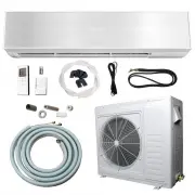
Page 4 Accessories 1 The air conditioning system comes with the following accessories. Use all of the installation parts and accessories to install the air conditioner. Improper installation may result in water leakage, electrical shock, or fire, or cause the equipment to fail. Name Shape Quanti...
Page 5 - Safety Precautions; Read safety precautions before installation; ARNING; or; • Carefully read the safety; designed air-conditioning units is highly recommended.; Note about Fluorinated Gasses; accordance with national regulations.; WARNING
Page 5 Safety Precautions 2 Read safety precautions before installation Incorrect installation due to ignoring instructions can cause serious damage or injury. The seriousness of potential damage or injuries is classified as either a W ARNING or CAUTION. WARNING • Carefully read the safety p rec...
Page 6 - Installation Overview; INSTALLA
Page 6 Installation Overview 3 Unit Installation Overview L N 1 2 3 MC MC 4 5 INSTALLA TION ORDER Install the outdoor unit (Page 9) Evacuate the refrigeration system (Page 20) Connect the wires (Page 14) Connect the refrigerant pipes (Page 12) Perform a test run (Page 22)
Page 7 - Installation Diagram; CAUTION
Page 7 Installation Diagram 4 Installation Diagram Fig. 4.1 Safety Precautions CAUTION • This illustration is for explanation purposes only. The actual shape of your air condtioner may be slightly different. Copper lines must be insulated independently. • CAUTION • To prevent unnecessary damage ...
Page 8 - Specifications; Indoor unit
T able 5.1 T able 5.2 Page 8 Specifications 5 Outdoor Unit Specifications Indoor units that can be used in combination Number of connected units 1-5 units Compressor stop/start frequency Stop time 3 minutes or more Voltage fluctuation within ± 10% of rated voltage Power source voltage Voltage dr...
Page 9 - Outdoor Unit Installation; Outdoor Unit Installation Instructions; Step 2: Install outdoor unit; Fix with bolts
Page 9 Outdoor Unit Installation Outdoor Unit Installation Outdoor Unit Installation Instructions Step 1: Select installation location When choosing a location to install the outdoor unit, consider the following: Place the outdoor unit as close to the indoor unit as possible. Ensure that the...
Page 11 - When Selecting a 24K Indoor Unit; Notes on Drilling the Hole in the Wall
Page 11 Outdoor Unit Installation When Selecting a 24K Indoor Unit The 24K indoor unit can only be connected with an A system. If there are two 24K indoor units, they can be connected with an A and B system (see Fig. 6.9). Fig. 6.9 T able 6.2: Connective pipe size of an A and B system (unit: inc...
Page 12 - Refrigerant Piping Connection Instructions; DO NOT; Step 3: Flare pipe ends
Page 12 Refrigerant Piping Connection 7 Safety Precautions WARNING • All field piping must be completed by a licensed technician and must comply with local and national regulations. • When the air conditioner is installed in a small room, measures must be taken to prevent the refrigerant concent...
Page 13 - FORM; NOTE ON MINIMUM BEND RADIUS; C AUTION
Page 13 4. Remove the PVC tape from the ends of the pipe when you're ready to perform the flaring work. 5. Clamp the flare form on the end of the pipe. The end of the pipe must extend beyond the flare form. Flare form Pipe Fig. 7.4 Refrigerant Piping Connection 6. Place the flaring tool onto the...
Page 14 - Rated Current of
Wiring Safety Precautions WARNING • Be sure to disconnect the power supply before working on the unit. • All electrical wiring must be done according to local and national regulations. • Electrical wiring must be done by a qualified technician. Improper connections may cause electrical malfunction, ...
Page 16 - Wiring Figure
Page 16 Wiring Figure Wiring NOTE: If the client wants to perform the wiring himself, refer to the following figures. Run the main power cord through the lower line-outlet of the cord clamp. CAUTION Connect the connective cables to the terminals as identified with their respective matched number...
Page 20 - VAL
Fig. 9.3 Page 20 Air Evacuation 9 Safety Precautions Evacuation Instructions Before using the manifold gauge or vacuum pump, read their operation manuals to familiarize yourself with how to use them properly. Manifold gauge Compound gauge -76 cmHg Low-pressure valve High-pressure valve Charge ho...
Page 22 - Before; est Run Instructions; est Run
Page 22 Test Run Before T est Run A test run must be performed after the entire system has been completely installed. Confirm the following points before performing the test: a) The indoor and outdoor units are properly installed. b) Piping and wiring are properly connected. c) No obstacles are ...
Page 23 - Automatic Wiring/Piping Correction Function; Function of Automatic Wiring/Piping Correction; How to Activate This Function; Check that the stop valves on the liquid and gas pipes are open.
Automatic Wiring/Piping Correction Function Page 23 Function of Automatic Wiring/Piping Correction 11 The new product is able to automatically correct a wiring/piping error. Press the "check switch" on the outdoor unit PCB board for 5 seconds until the LED display shows "CE." Thi...
Page 25 - MULTI·ZONE; DUCTLESS INVERTER; SPLIT AIR CONDITIONER; MANUAL«; OUTDOOR CONDENSER; OUTDOOR UNIT
MULTI·ZONE DUCTLESS INVERTER SPLIT AIR CONDITIONER WITH HEAT PUMP »OWNER'S MANUAL« OUTDOOR CONDENSER IMPORTANT NOTE: • Read this manual carefully before installing or operating your new air conditioning unit. Make sure to save this manual for future reference. • This manual only describes features o...
Page 26 - Owner’s Manual; SAFETY
Unit Parts and Major Functions ......................... 05 Manual Operation and Maintenance .............. 09 T able of Contents Owner’s Manual SAFETY FIRST Safety Precautions .................................................... 04 1 2 3
Page 27 - Troubleshooting
Page 3 Troubleshooting ................................. 10 a. Common Problems ................................. 10 b. Troubleshooting Tips ............................... 11 4
Page 28 - Safety P
Page 4 Thank you for purchasing this air conditioner. This manual will provide you with information on how to operate, maintain, and troubleshoot your air conditioner. Following the instructions will ensure the proper function and extended lifespan of your unit. Please pay attention to the follo...
Page 29 - Unit Parts And Major Functions; Unit Parts
Page 5 Unit Parts And Major Functions 2 Unit Parts Fig. 2.1 Fig. 2.2 Unit Parts And Major Functions Wall-mounted type Duct / Ceiling type Indoor unit 1. Panel frame 2. Rear air intake grille 3. Front panel 4. Air Purifying filter & Air filter(behind) 5. Horizontal louver 6. LCD display windo...
Page 30 - Compact four-way cassette type
Fig. 2.3 Page 6 Unit Parts And Major Functions Floor and standing type(console) Compact four-way cassette type Indoor unit 1. Air flow louver (at air outlet) 2. Air inlet(containing air filter) 3. Remote controller 4. Installation part 5. Display panel Outdoor unit 6. Drain hose, refrigerant con...
Page 33 - Manual Operations And Maintenance; • Do not place any object near the air inlet or air
Manual Operations And Maintenance Page 9 Manual Operations And Maintenance 3 Operation mode selection Maintenance While two or more indoor units are simultaneously operating, make sure the modes do not conflict with each other. The heat mode claims precedence over all other modes. If the unit in...
Page 34 - CAUTIONS; oblem; oubleshooting
Page 10 Troubleshooting CAUTIONS If one of the following conditions occurs, switch off the power supply immediately and contact your dealer for further assistance. • The operation light continues to flash rapidly after the unit has been restarted. • The remote control buttons do not work. • The ...
Page 36 - to work harder and longer to hold the selected room; indoor evaporator’s; SYSTEMOPERATION
COOLING OPERATION How it works:In cooling mode, your indoor evaporator will absorb heat from the room, then the outdoor condenser will discharge the heat to the outdoors. The sophia cooling capacity decreases as the outdoor temperature increases. This causes the ali ce to work harder and longer to h...
Page 37 - ENERGY SAVING TIPS; Relaxing room temperatureat night is OK:
ENERGY SAVING TIPS 1. Relaxing room temperatureat night is OK: During the nighttime hours you don’t require the same level of conscious cooling or heating.Try using Sleep Mode to gradually relax room temperature and allow theunit to run less and save energy. 2. Curtains and shades: In the summer, yo...