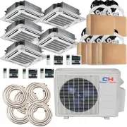
Ramsond CH09/09/09/09/MSPHCT230VI-CH36MSPH230VOA - Manuals
Ramsond CH09/09/09/09/MSPHCT230VI-CH36MSPH230VOA Air Conditioner – User Manual in PDF format online.
Manuals:
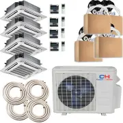
User Manual Ramsond CH09/09/09/09/MSPHCT230VI-CH36MSPH230VOA


Summary
User Notice ◆ When operating, the entire capacity of the cooperating indoor unit should be not larger than 150% of outdoor unit. Otherwise, it will cause the shortage of cooling (heating) capacity. ◆ A Breaker(or fuse) need to be installed in every indoor unit, and the capacity should in according w...
Contents 1 Safety Information . .................................................................................... 1 2 Install of The Compact Panel Cassette Type Indoor Unit . ......................... 2 2.1 Schematic diagram of installation spaces . ..................................................
Safety Information 1 1 Safety Information Please read this manual carefully before use this unit, and operate it correctly according to the guide in this manual. Please take specially note to the meaning of these two marks: Warning!: This mark means that it may cause casualty or badly heart if the o...
Ramsond Air Conditioners Manuals
-
 Ramsond 101GWi
User Manual
Ramsond 101GWi
User Manual
-
 Ramsond 27GW2
User Manual
Ramsond 27GW2
User Manual
-
 Ramsond 27SEG
User Manual
Ramsond 27SEG
User Manual
-
 Ramsond 37GW2
User Manual
Ramsond 37GW2
User Manual
-
 Ramsond 37GWi
User Manual
Ramsond 37GWi
User Manual
-
 Ramsond 37GWX
User Manual
Ramsond 37GWX
User Manual
-
 Ramsond 37SEG
User Manual
Ramsond 37SEG
User Manual
-
 Ramsond 55GWi
User Manual
Ramsond 55GWi
User Manual
-
 Ramsond 74GW2
User Manual
Ramsond 74GW2
User Manual
-
 Ramsond 74GWi
User Manual
Ramsond 74GWi
User Manual
-
 Ramsond CH09/09/09/09/09MSPHCT230VI-CH48MSPH230V
User Manual
Ramsond CH09/09/09/09/09MSPHCT230VI-CH48MSPH230V
User Manual
-
 Ramsond CH09/09/09/09/09MSPHWM230VI-CH48MSPH230V
User Manual
Ramsond CH09/09/09/09/09MSPHWM230VI-CH48MSPH230V
User Manual
-
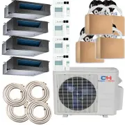 Ramsond CH09/09/09/09MSPHDT230VI-CH36MSPH230VOA
User Manual
Ramsond CH09/09/09/09MSPHDT230VI-CH36MSPH230VOA
User Manual
-
 Ramsond CH09/09/09/09MSPHWM230VI-CH36MSPH230VOA
User Manual
Ramsond CH09/09/09/09MSPHWM230VI-CH36MSPH230VOA
User Manual
-
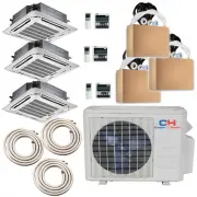 Ramsond CH09/09/09MSPHCT230VI-CH27MSPH230VOA
User Manual
Ramsond CH09/09/09MSPHCT230VI-CH27MSPH230VOA
User Manual
-
 Ramsond CH09/09/09MSPHDT230VI-CH27MSPH230VOA
User Manual
Ramsond CH09/09/09MSPHDT230VI-CH27MSPH230VOA
User Manual
-
 Ramsond CH09/09/09MSPHWM230VI-CH27MSPH230VOA
User Manual
Ramsond CH09/09/09MSPHWM230VI-CH27MSPH230VOA
User Manual
-
 Ramsond CH09/09MSPHCT230VI-CH18MSPH230VOA
User Manual
Ramsond CH09/09MSPHCT230VI-CH18MSPH230VOA
User Manual
-
 Ramsond RH5Z-48-5X12WM
User Manual
Ramsond RH5Z-48-5X12WM
User Manual
-
 Ramsond RH5Z-48-5X9WM
User Manual
Ramsond RH5Z-48-5X9WM
User Manual