Page 2 - CONTENTS
CONTENTS SAFETY PRECAUTIONS................................................................ 1NAMES OF THE PARTS................................................................ 3INDOOR UNIT DISPLAY............................................................... 4EMERGENCY FUNCTION & AUTO -RESTART ...
Page 5 - NAMES OF THE PARTS
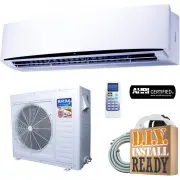
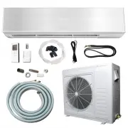
3 NOTE: the above figures are only intended to be a simplediagram of the overall units and may not correspond to theappearance of the units purchased. • The air conditioner is made up of two or more units connected to each other through copper pipes (properly insulated) and an electrical connecting ...
Page 6 - INDOOR UNIT DISPLAY
4 Unit working RUN 5 TIMER mode TIMER 4 Indicates the set temperature in C° or F° Temperature display (if present) 3 SLEEP mode SLEEP 2 Shows that the unit is powered POWER 1 Function Led No. INDOOR UNIT DISPLAY 1 2 3 4 5
Page 7 - EMERGENCY FUNCTION AND AUTO-RESTART FUNCTION
Emergency Button 5 Emergency Button EMERGENCY FUNCTION AND AUTO-RESTART FUNCTION AUTO-RESTART FUNCTION The appliance comes equipped with a preset Auto- Restart function by the manufacturer. Using this function, the air conditioner can keep the selected settings after a blackout or a voltage drop. To...
Page 8 - REMOTE CONTROL
6 Note: each mode and relevant function will be further specified in following pages. Transmits signals to the system. Signal Transmitting Window Temperature Adjustment (All modes) ( ˚ C ˚ F ) Temperature ( h ) Timer Setting Mode Transmitting Icon Setting Display ON/OFF Button Starts and stops opera...
Page 9 - Guide to LCD Symbols; Remote Control Display
7 FEEL mode COOL mode DRY mode FAN ONLY mode HEATING mode TRANSMIT SIGNAL TIMER OFF TIMER ON AUTO FAN mode LOW FAN mode MEDIUM FAN mode HIGH FAN mode SLEEP mode FLAP SWING mode 1 2 3 4 5 6 7 8 9 10 11 12 13 14 Indicator No. Symbols Guide to LCD Symbols Remote Control Display REMOTE CONTROL
Page 10 - To Use; REMOTE CONTROL PROGRAMMING
Preliminary Instructions How to Insert the Batteries • See Diagram 1 : Remove the cover from the battery compartment by sliding it in the direction of the arrow. • Insert the new batteries, ensuring that the (+) and (-) symbols are correct. • Replace the cover by sliding it into place. Use 2 LRO 3 A...
Page 11 - MODES OF OPERATION; ‘SWING’ CONTROL OF AIR FLOW
‘Flaps’ Deflectors Filter Fan Heat Exchanger A IR S WING 9 MODES OF OPERATION This air conditioner is designed to create a comfortable climate for individuals in the affected room. All models can cool and dehumidify the air completely automatically and some models can also provide heat using either ...
Page 12 - COOLING MODE
10 COOLING MODE The cooling function allows the air conditionerto cool the room while dehumidifying the air atthe same time. To activate the cooling function (COOL), press the MODEbutton until the symbol (COOL) appears on the LCDdisplay. The cooling cycle is activated by using the or keysto set the ...
Page 14 - FAN MODE
12 MODES OF OPERATION FAN MODE DRY MODE The system can be set to run in FAN mode,providing ventilation only. To run the system in FAN mode, press the MODEbutton until the FAN symbol appears on thedisplay. Pressing the FAN button while in this modechanges the fan speed to LOW, MEDIUM, HIGH,or AUTO. T...
Page 16 - PROTECTION
2 1 3 Heating For T1 Climate condition models: 14 No. MODEL 2 1 3 No. MODEL PROTECTION In the cases listed below, the built-in protective device may be tripped,causing the system to stop operation. For Tropical (T3) Climate condition models: Heating Cooling Cooling Dry Dry Outdoor air temperature is...
Page 17 - Installation Diagram; INDOOR UNIT
INSTALLATION MANUAL---Selecting the Installation Place Install the indoor unit level on a strong wall that is not subject to vibrations. The inlet and outlet ports should not be obstructed:the air should be able to blow all over the room. Do not install the unit near a source of heat , steam,or flam...
Page 18 - wiring diagram; Installation of the mounting plate
INSTALLATION MANUAL---Installation of the Indoor unit 1. By using a level, put the mounting plate in a perfect square position vertically and horizontally.2. Drill 32 mm deep holes in the wall to fix the plate;3. Insert the plastic anchors into the hole;4. Fix the mounting plate by using the provide...
Page 20 - INSTALLATION OF THE INDOOR UNIT
INSTALLATION MANUAL---Installation of the Indoor unit INSTALLATION OF THE INDOOR UNIT refrigerant pipe refrigerant pipe insulation sleeve connection (for heat-pump) cable 1 connection cable Probe cable(for heat-pump) Condensed waterdrain pipe Covered by vinyl tape After having connected the pipe acc...
Page 22 - Indoor unit test; BLEEDING
INSTALLATION MANUAL---Installation of the outdoor unit The air and humidity left inside the refrigerant circulat-ion can cause compressor malfunction. After having co-nnected the indoor and outdoor units, bleed the air and humidity from the refrigerant circulation using a va-cuum pump. Refrigerant f...
Page 23 - PIPE
INSTALLATION MANUAL---Information for the installer (1) Refer to the data rating label sticked on the outdoor unit. TIGHTENING TORQUE FOR PROTECTION CAPS AND FLANGE CONNECTION 21 MODEL capacity (Btu/h) 7k 9k 12k 15/18k 22/24k 28/30k Liquid pipe diameter Gas pipe diameter Lenght of pipe with standard...
Page 24 - WIRING DIAGRAM; Please see the pasted diagram instruction on the unit first
INSTALLATION MANUAL---Information for the installer O U T D O O R U N I T I N D O O R U N I T P O W E R S U P P L Y O U T D O O R U N I T I N D O O R U N I T P O W E R S U P P L Y WIRING DIAGRAM FOR 9K-12K-18K-24K COOLING ONLY MODELS FOR 9K-12K-18K-24K HEAT PUMP MODELS Note: The cable wires hasbeen ...
Page 25 - CABLE WIRES SPECIFICATION; Power supply cable
INSTALLATION MANUAL---Information for the installer CABLE WIRES SPECIFICATION Type for 220V of fuse used on indoor unit controller for 7K , 9K , 12K 15K , 16K , 18K , 22K , 24K , 30K is 50T with rating 3.15 A , 250V Type for 110V of fuse used on indoor unit controller for 7K , 9K 12k is 50T with rat...
Page 26 - MAINTENANCE; off; ANTIDUST FILTERS; CLEANING THE HEAT EXCHANGER; antidust filter
MAINTENANCE Periodic maintenance is essential for keeping your air conditioner efficient.Before carrying out any maintenance , disconnect the power supply by putting the installation on/ off switch to off . INDOOR UNIT ANTIDUST FILTERS 1. Open the front panel following the direction of the arrow2. K...
Page 27 - TROUBLESHOOTING; MALFUNCTION; Strange odour; ERROR SIGNALS ON THE DISPLAY; Malfunction of indoor fan motor.
TROUBLESHOOTING 25 MALFUNCTION Strange odour The appliance does not operate Noise of running water A fine mist comes from the air outlet Insufficient airflow, eitherhot or cold The appliance does not respond to commands The display is off Switch off the air condi- tioner immediately and cut off the ...