Page 2 - CONTENTS; Q C M A N U FA C T U R I N G , I N C .
1-888-QUIETCOOL 2 CONTENTS 1. SYSTEM OVERVIEW . . . . . . . . . . . . . . . . . . . . . . . . . . . . . . . . . . . . . . . 3 1.1 Introduction . . . . . . . . . . . . . . . . . . . . . . . . . . . . . . . . . . . . . . . . . 31.2 Features . . . . . . . . . . . . . . . . . . . . . . . . . . . . . . ....
Page 3 - CONGRATULATIONS; on the purchase of your new QuietCool Garage Fan!
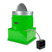
QUIETCOOLSYSTEMS.COM 3 1. SYSTEM OVERVIEW 1.1 INTRODUCTION CONGRATULATIONS on the purchase of your new QuietCool Garage Fan! The QuietCool Garage Fans offer great ventilation options for your garage, man cave, or workshop. We offer the GA ES-1500 Garage Whole House Fan to ventilate both your garage ...
Page 4 - SYSTEM VENTING REQUIREMENTS; SQUARE FOOT OF NET FREE VENT AREA PER 750 CFM; Vent Type
1-888-QUIETCOOL 4 1.3 SYSTEM VENTING REQUIREMENTS VERY IMPORTANT: 1 SQUARE FOOT OF NET FREE VENT AREA PER 750 CFM RECOMMENDED: 2 TO 4 SQUARE FEET OF INLET VENTS PER FAN Venting plays a very significant role in the performace of QuietCool fans. QuietCool recommends a mini- mum of 1 SQ. FT. of venting...
Page 5 - GETTING STARTED; BEFORE attempting installation.; GENERAL SAFETY INFORMATION; - All safety and operation instructions must be read.; RETAIN INSTRUCTIONS; - All installation and operating instructions should be followed.; DAMAGE REQUIRING SERVICE; The user should not attempt to service the product.; WARNINGS; solid state speed control device. For residential use only.; INCLUDED IN THE BOX; HARDWARE KIT CONTENTS
QUIETCOOLSYSTEMS.COM 5 WELCOME INST ALLA TION WIRING OPERA TION W ARRANTY READ ALL INSTRUCTIONS IN THIS GUIDE BEFORE INSTALLING YOUR QUIETCOOL GETTING STARTED STOP! Read the following pages before proceeding! The manufacturer is NOT responsible for faulty installation or product damages caused throu...
Page 9 - POWER INDICATOR; FAN HUB LED INDICATORS
QUIETCOOLSYSTEMS.COM 9 WELCOME INST ALLA TION WIRING OPERA TION W ARRANTY PowerCord Attach green ground wires to ground screw All White Common Wires Together POWER TIMER PAIR TEST Set dip switches: 1 - ON 2 - OFF3 - OFF Attic Fan ON 1 2 3 Figure 3.1A POWER TIMER PAIR TEST POWER INDICATOR • The Power...
Page 10 - PAIRING THE WALL SWITCH; indicating that the switch has power. Replace the front cover.; pairing. You will need to go back and repeat steps 4 and 5.
1-888-QUIETCOOL 10 3.3 PAIRING THE WALL SWITCH 1. Using a flat-head screwdriver, remove the front cover off the wall switch. 2. Install the included AAA batteries into the switch. All the LED indicators will light up indicating that the switch has power. Replace the front cover. 3. Press and hold th...
Page 11 - INSTALLING THE WALL SWITCH
QUIETCOOLSYSTEMS.COM 11 3.4 FINDING A LOCATION FOR THE WALL SWITCH 1. It is very important to find the correct location to install the Wall Switch that will allow the Wall Switch to communicate with the Hub. 2. Find the location you would like to install the Wall Switch and test that it properly com...
Page 12 - SYSTEM OPERATING INSTRUCTIONS; OPERATING THE WALL SWITCH; TIMER BUTTON; WALL SWITCH SLEEP MODE; NOTE ON OPERATION; FREQUENTLY ASKED QUESTIONS
1-888-QUIETCOOL 12 1 2 4 8 12 H M L 4. SYSTEM OPERATING INSTRUCTIONS 4.1 OPERATING THE WALL SWITCH TIMER BUTTON • The top button on the switch controls the Timer functionality of the fan. • This button must be pressed for the fan to turn on. • To turn the fan off, you must cycle through the time set...
Page 14 - GARAGE FANS LIMITED WARRANTY
1-888-QUIETCOOL 14 GARAGE FANS LIMITED WARRANTY This warranty is extended to the original purchaser of this model or, if this unit is purchased and requires installation by a building contractor, to the original owner of the home. No subsequent purchaser of the unit or of a home in which it is insta...
Page 16 - SERIAL NUMBER IS REQUIRED FOR WARRANTY PURPOSES.
FAN SERIAL NUMBER INFORMATION RETAIN FOR YOUR RECORDS. SERIAL NUMBER IS REQUIRED FOR WARRANTY PURPOSES. 1-888-QUIETCOOL | WWW.QUIETCOOLSYSTEMS.COM Rev. 8/30/23