Page 2 - Powernail Company Info 12
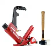
2 The Model 50F trigger-pull nailer is designed to bring Powernail quality and fl ooring expertise to a pneumatic nailer. The Model 50F is designed for use with 1-1/4” to 1-3/4”, 18 gauge L-Cleat Powernails®. The Model 50F nails from 3/8” to 3/4” fl ooring through the use of a FLEX adjustable foot ass...
Page 3 - SAFETY INSTRUCTIONS; Noise characteristic values in accordance with ENxx1:; Weighted root mean square acceleration 3.2m/s2
Always DISCONNECT THE AIR SUPPLY before making any adjustments, repairing, clearing jams or when the Nailer is not in use. Do not use on scaff olding or ladders and disconnect nailer from air supply when transporting between installation areas. Never attach the female end of a quick disconnect to the...
Page 4 - OPERATION; The Model 50F installs
4 The Model 50F nails down fl ooring from 3/8” to 3/4” using the Powernail FLEX adjustable foot assembly that can be adjusted to fi t diff erent fl ooring profi les.To use the Model 50F, properly position the tool on the fl ooring plank (See picture below) . Pull up and hold the black safety trigger to ac...
Page 5 - If your FLEX foot is not tight enough:; and turning it from right to left; FLEX Foot Adjustment; How to adjust your tool’s foot to your fl oor’s thickness:
5 Use the photos on the right for reference:1.) First loosen the tool’s FLEX foot by turning the lever from right to left/counter clockwise. (See image 1.a) a.) The FLEX foot should now freely slide up-and-down the magazine. 2.) Using a sample of your fl ooring, slide the FLEX foot back on the channe...
Page 6 - LOADING THE FASTENERS; Air Hose
6 1.) Insert a full stick of 1-1/4”, 1-1/2” or 1-3/4” 18 gauge Powercleats through the slotted Magazine Rear Cover(49) into the Magazine (47) OPERATION, continued... Figure 4. Figure 5. (Figure 4) 2.) Pull back the spring loaded Nail Pusher (39) over the nails until it contacts the last nail and slo...
Page 7 - REGULAR MAINTENANCE; MAINTENANCE
REGULAR MAINTENANCE 1.) Frequent, but not excessive, lubrication is required for best performance. Oil added through the airline connection will lubricate internal parts. An automatic airline oilier is recommended but oil may be added manually before every operation or after about 8 hours of continu...
Page 8 - CLEARING A JAM
8 CLEARING A JAM Disassembly: (See Figure 7.) 1) NOTE: Do not remove the four M4 screws (80). 2) Loosen the 4 M4 screws (78) with a 3mm allen wrench.3) Slide the gate plate down until it is free from the nose..6) Lift the gate plate (72) off .5) Inspect and clear any debris from the drive blade (27) ...
Page 9 - TROUBLE SHOOTING CHART
PROBLEM POSSIBLE CAUSE SOLUTION 1 Air leaking at Trigger area 1. O-ring (34) in trigger valve is damaged.2. Trigger valve head (34) is damaged. 3. Trigger valve stem, seal or O-ring (34) is damaged. 1. Check and replace O-ring.2. Check and replace triggervalve head.3. Check and replace trigger valve...
Page 10 - MODEL 50F PARTS LIST
10 MODEL 50F PARTS LIST KEY: S=Sold Separately, N/A= Not available separately, KIT=Sold as part of a Kit, ITEM DESCRIPTION Avail. QTY PART # 1 UM.HD.BOLT S 1 09-50F001 2 FLAT WASHER S 1 09-50F002 3 EXHAUST COVER, METAL S 1 09-50F003 4 SEAL S 1 09-50F004 5 HEX.SOC.HD.BOLT+SW S 4 09-50F005 6 CAP S 1 0...
Page 11 - MODEL 50F SCHEMATIC
Page 12 - tested in the fi eld before proceeding.; POWERCLEATS LENGTH DETERMINATION CHART; 8 GA HD POWERCLEATS
POWERNAIL COMPANY, INC. 1300 Rose Road, Lake Zurich, IL 60047 US Phone: 1-800-323-1653 or 847-847-3000 www.powernail.com ©Powernail Company 2017 This chart will assist you in determining the proper length of Powercleats to use for various thicknesses of fl ooring. Approximate vertical penetration of ...