NordicTrack NTSY19916 - Manuals
NordicTrack NTSY19916 – User Manual in PDF format online.
Manuals:
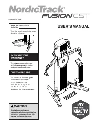
User Manual NordicTrack NTSY19916
1
2

3

4

5

6

7

8

9

10

11

12

13

14

15

16

17

18

19

20

21

22

23

24

Summary
Page 2 - WARNING DECAL PLACEMENT
2 This drawing shows the location(s) of the warning decal(s). If a decal is missing or illegible, see the front cover of this manual and request a free replacement decal. Apply the decal in the location shown. Note: The decal(s) may not be shown at actual size. WARNING DECAL PLACEMENT . . . . . . . ...
Page 3 - IMPORTANT PRECAUTIONS
3 IMPORTANT PRECAUTIONS WARNING: To reduce the risk of serious injury, read all important precautions and instructions in this manual and all warnings on your strength system before using your strength system. ICON assumes no responsibility for personal injury or property damage sustained by or thro...
Page 4 - STANDARD SERVICE PLANS
NordicTrack Manuals
-
 NordicTrack NTL10840
User Manual
NordicTrack NTL10840
User Manual
-
NordicTrack NTL10840
Manual
-
 NordicTrack NTL12951
User Manual
NordicTrack NTL12951
User Manual
-
NordicTrack NTL12951
Manual
-
 NordicTrack NTL12942
User Manual
NordicTrack NTL12942
User Manual
-
NordicTrack NTL12942
Manual
-
 NordicTrack NTL12943
User Manual
NordicTrack NTL12943
User Manual
-
NordicTrack NTL12943
Manual
-
 NordicTrack NTL12940
User Manual
NordicTrack NTL12940
User Manual
-
NordicTrack NTL12940
Manual
-
 NordicTrack NTL10841
User Manual
NordicTrack NTL10841
User Manual
-
NordicTrack NTL10841
Manual
-
 NordicTrack NTL12952
User Manual
NordicTrack NTL12952
User Manual
-
 NordicTrack NTL12941
User Manual
NordicTrack NTL12941
User Manual
-
NordicTrack NTL12941
Manual
-
 NordicTrack NTL12950
User Manual
NordicTrack NTL12950
User Manual
-
NordicTrack NTL12950
Manual
-
 NordicTrack NTTL11994
User Manual
NordicTrack NTTL11994
User Manual
-
NordicTrack NTTL11994
Manual
-
 NordicTrack NTTL15993
User Manual
NordicTrack NTTL15993
User Manual