Page 3 - TABLE OF CONTENTS; Page; GENERAL; Removing The Heater, High-Limit Thermostat, And Thermal Cutoff; COMPONENT TESTING
- iii - TABLE OF CONTENTS Page GENERAL . . . . . . . . . . . . . . . . . . . . . . . . . . . . . . . . . . . . . . . . . . . . . . . . . . . . . . . . . . . . . . 1-1 Dryer Safety. . . . . . . . . . . . . . . . . . . . . . . . . . . . . . . . . . . . . . . . . . . . . . . . . . . . . . . . . . . . 1...
Page 4 - DIAGNOSTICS & TROUBLESHOOTING
- iv - Page DIAGNOSTICS & TROUBLESHOOTING . . . . . . . . . . . . . . . . . . . . . . . . . . . . . . . . . . . . . . 6-1 Diagnostic Guide . . . . . . . . . . . . . . . . . . . . . . . . . . . . . . . . . . . . . . . . . . . . . . . . . . . . . . . . 6-1 Diagnostic Tests . . . . . . . . . . . . ...
Page 5 - DRYER SAFETY; Your safety and the safety of others are very important.; Always read and obey all safety messages.; You can be killed or seriously injured if you don’t; DANGER
1-1 GENERAL DRYER SAFETY Your safety and the safety of others are very important. We have provided many important safety messages in this manual and on the appliance. Always read and obey all safety messages. This is the safety alert symbol.This symbol alerts you to potential hazards that can kill o...
Page 6 - MODEL & SERIAL NUMBER DESIGNATIONS
1-2 SERIAL NUMBER C U 35 10901 DIVISION RESPONSIBILITY C = CLYDE, OH YEAR OF PRODUCTION U = 2007 WEEK OF PRODUCTION 35 = 35th Week PRODUCT SEQUENCE NUMBER MODEL NUMBER M E D Z 6 00 T W 00 BRAND M = Maytag FUEL E = Electric PRODUCT D = Dryer PRICE POINT LEVELS (1 - 9) TRADE PARTNER ID (00 = BRANDED)Y...
Page 8 - SPECIFICATIONS
1-4 SPECIFICATIONS Model Number MEDZ600TW00 MGD600TW00 Model Description Matching Dryer For Front Load Washer Color White Capacity (Cu.Ft. IEC) 6.7 Venting 4 way Reversible Door Yes Lint Screen Location Front Height 36.0" Install Depth: Min - Max 28.90" - 32.90" Width 27" Product Wei...
Page 9 - INSTALLATION INFORMATION; INSTALLATION INSTRUCTIONS; TOOLS AND PARTS; Electric Models; Parts Supplied
2-1 INSTALLATION INFORMATION INSTALLATION INSTRUCTIONS TOOLS AND PARTS Gather the required tools and parts before starting installation. Read and follow the safe- ty instructions provided with any tools listed here. Electric Models Flat-blade screwdriver • #2 Phillips screwdriver • Adjustable wrench...
Page 10 - WARNING; LOCATION REQUIREMENTS; Explosion Hazard; OPTIONS; Pedestal
2-2 WARNING LOCATION REQUIREMENTS Explosion Hazard Keep flammable materials and vapors, such as gasoline, away from dryer.Place dryer at least 18 inches (46 cm) above the floor for a garage installation.Failure to do so can result in death, explosion, or fire. You will need A location that allows fo...
Page 16 - Style 2: Direct wire strain relief; Electrical Connection Options
2-8 Put power supply cord through the strain • relief. Be sure that the wire insulation on the power supply cord is inside the strain relief. The strain relief should have a tight fit with the dryer cabinet and be in a hori- zontal position. Do not further tighten strain relief screws at this point....
Page 19 - cabinet-ground conductor to neutral wire.
2-11 4. Place the hooked ends of the other direct wire cable wires under the outer terminal block screws (hooks facing right). Squeeze hooked ends together. Tighten screws. 5. Tighten strain relief screw.6. Insert tab of terminal block cover into slot of dryer rear panel. Secure cover with hold-down...
Page 21 - GAS SUPPLY REQUIREMENTS
2-13 3. Connect the other wires to outer terminal block screws. Tighten screws. 4. Tighten strain relief screws.5. Connect a separate copper ground wire from the external ground conductor screw to an adequate ground. 6. You have completed your electrical connec- tion. Now go to “Venting Requirements...
Page 22 - Gas supply line; Gas supply connection requirements
2-14 Gas TypeNatural gas: This dryer is equipped for use with Natural gas. It is design-certified by CSA International for LP (propane or butane) gases with appro- priate conversion.This dryer must have the correct burner for the type of gas in your home. Burner informa- tion is located on the ratin...
Page 23 - Gas supply pressure testing; Fire Hazard; VENTING REQUIREMENTS
2-15 Option 2 (Alternate method) Approved aluminum or copper tubing: Lengths under 20 ft (6.1 m) can use 3/8 • ˝ approved tubing (if codes and gas supplier permit).If you are using Natural gas, do not use • copper tubing.3/8 • ˝ flare x 3/8 ˝ NPT adapter fitting be- tween dryer pipe and 3/8 ˝ approv...
Page 25 - PLAN VENT SYSTEM
2-17 Improper venting can cause moisture and lint to collect indoors, which may result in: Moisture damage to woodwork, furni- • ture, paint, wallpaper, carpets, etc.Housecleaning problems and health • problems. PLAN VENT SYSTEM Choose your exhaust installation typeRecommended exhaust installations ...
Page 26 - INSTALL VENT SYSTEM; Special provisions for mobile home
2-18 Number of 90º turns or elbows Type of vent Box or louvered hoods Angled hoods 0 Rigid metal Flexible metal 64 ft (20 m) 36 ft (11 m) 58 ft (17.7 m) 28 ft (8.5 m) 1 Rigid metal Flexible metal 54 ft (16.5 m) 31 ft (9.4 m) 48 ft (14.6 m) 23 ft (7 m) 2 Rigid metal Flexible metal 44 ft (13.4 m) 27 f...
Page 27 - Excessive Weight Hazard; INSTALL LEVELING LEGS; For mobile home use; MAKE GAS CONNECTION
2-19 WARNING Excessive Weight Hazard Use two or more people to move and install dryer.Failure to do so can result in back or other injury. INSTALL LEVELING LEGS 3. Examine the leveling legs. Find the dia- mond marking. 1. To protect the floor, use a large flat piece of cardboard from the dryer carto...
Page 30 - COMPLETE INSTALLATION
2-22 4. Reinstall plug strips on opposite side of the inner door. 5. Check for fingerprints on the glass. Clean glass if necessary. 6. Place the inner door assembly inside the outer door assembly. To fit correctly, the inner door assembly edge fits completely inside the outer door assembly edge. 7. ...
Page 32 - — NOTES —
Page 33 - DRYER USE; PRODUCT OPERATION; STARTING THE DRYER
3-1 DRYER USE PRODUCT OPERATION WARNING Explosion Hazard Keep flammable materials and vapors, such as gasoline, away from dryer.Do not dry anything that has ever had anything flammable on it (even after washing).Failure to follow these instructions can result in death, explosion, or fire. STARTING T...
Page 34 - Follow these basic steps to start your dryer.
3-2 Follow these basic steps to start your dryer. Please refer to specific sections of this manual for more detailed information.1. Clean lint screen before each load. See “Cleaning the Lint Screen.” 2. Place laundry into dryer and shut door. 3. Press POWER. 4. Select a Sensor Dry or Timed Dry Cycle...
Page 36 - WRINKLE PREVENT; STATUS LIGHTS; Jeans
3-4 Wet The Wet light illuminates at the beginning of an Auto Cycle if a wet item is detected In an Sensor Dry Cycle, if a wet item is not • detected after approximately 5 minutes, the dryer goes directly into Cool Down and the Cool Down and WRINKLE PREVENT indica - tors illuminate, if selected.In a...
Page 37 - Timed Dry Cycles; Freshen Up; ting. Time will vary depending on load type and
3-5 Wrinkle Control Use this cycle to get low heat for drying no-iron fabrics such as sport shirts, casual business clothes and permanent press blends. Delicate Use this cycle to get Low heat for drying syn - thetic fabrics, washable knit fabrics and no-iron finishes. Sensor Dry Cycles Preset Settin...
Page 38 - ADDITIONAL FEATURES; Temperature; Cycle Signal
3-6 ADDITIONAL FEATURES Temperature Temperature settings are used with the Timed Dry Cycles. Press TEMPERATURE until the desired temperature setting illuminates. Temperature settings cannot be used with the Sensor Dry Cycles Air Fluff Use the Air Fluff temperature setting for items that require dryi...
Page 39 - Changing Cycles after pressing Start; DRYING RACK OPTION; To use the drying rack
3-7 CHANGING CYCLES, OPTIONS AND MODIFIERS Changing Cycles after pressing Start 1. Press PAUSE/CANCEL twice. This ends the current cycle. 2. Select the desired cycle and options.3. Press and hold START. The dryer starts at the beginning of the new cycle. NOTE: If you do not press Start within 5 minu...
Page 41 - DRYER CARE; CLEANING THE LINT SCREEN; Every load cleaning; CLEANING THE DRYER LOCATION; As needed cleaning; or cause the dryer to stop before your load is; To wash
3-9 DRYER CARE WARNING Explosion Hazard Keep flammable materials and vapors, such as gasoline, away from dryer.Place dryer at least 18 inches (46 cm) above the floor for a garage installation.Failure to do so can result in death, explosion, or fire. CLEANING THE LINT SCREEN Every load cleaning The l...
Page 42 - CLEANING THE DRYER INTERIOR; To clean dryer drum; REMOVING ACCUMULATED LINT; From Inside the Dryer Cabinet; VACATION AND MOVING CARE; Vacation care
3-10 CLEANING THE DRYER INTERIOR To clean dryer drum 1. Make a paste with powdered laundry de - tergent and very warm water. 2. Apply paste to a soft cloth. OR Apply a liquid, nonflammable household cleaner to the stained area and rub with a soft cloth until all excess dye and stains are removed. 3....
Page 43 - TROUBLESHOOTING; Unusual sounds; DRYER OPERATION
3-11 TROUBLESHOOTING Dryer will not run Has a household fuse blown, or has a • circuit breaker tripped? There may be 2 fuses or circuit breakers for the dryer. Check that both fuses are intact and tight, or that both circuit breakers have not tripped. Replace the fuse or reset the circuit breaker. I...
Page 44 - DRYER RESULTS; the rear of the dryer requires 5; Use 4
3-12 DRYER RESULTS Clothes are not drying satisfactorily, drying times are too long, or load is too hot Is the lint screen clogged with lint? • Lint screen should be cleaned before each load. Is the dryer located in a room with tem - • perature below 45 ° F (7 ° C)? Proper operation of dryer cycles ...
Page 45 - Odors
3-13 Lint on load Is the lint screen clogged? • Clean lint screen. Check for air movement. Stains on load or drum Was dryer fabric softener properly • used? Add dryer fabric softener sheets at the be - ginning of the cycle. Fabric softener sheets added to a partially dried load can stain your garmen...
Page 47 - COMPONENT ACCESS; COMPONENT LOCATIONS; Electric Heater
4-1 COMPONENT ACCESS COMPONENT LOCATIONS This section instructs you on how to service each component inside the Maytag Epic z ™ Elec- tronic Gas & Electric Dryers. The components and their locations are shown below. Flame Sensor Drum Light High-Limit Thermostat Gas Burner Rear Drum Rollers Drive...
Page 48 - Electrical Shock Hazard; REMOVING THE CONSOLE AND; To remove the console:
4-2 Electrical Shock Hazard Disconnect power before servicing.Replace all parts and panels before operating.Failure to do so can result in death or electrical shock. 1. Unplug dryer or disconnect power.2. Turn off gas supply to dryer.3. Remove the rear screws from the top cover of the dryer. 4. Lift...
Page 49 - To remove the console electronics as-; a) Pull the selector knob off the switch
4-3 6. To remove the console electronics as- sembly: a) Pull the selector knob off the switch shaft. b) Press the seven console locking tabs, and unsnap the console electronics assembly, then lift the assembly from the console and remove it. Console Locking Tabs Console Electronics Assembly Remove S...
Page 50 - REMOVING THE MACHINE CONTROL ELECTRONICS
4-4 Electrical Shock Hazard Disconnect power before servicing.Replace all parts and panels before operating.Failure to do so can result in death or electrical shock. 1. Unplug dryer or disconnect power.2. Turn off gas supply to dryer.3. Remove the rear screws from the top cover of the dryer. 4. Lift...
Page 51 - panel cutout. If necessary, press a small; REMOVING THE DOOR SWITCH; Disconnect the wires from the door switch
4-5 Electrical Shock Hazard Disconnect power before servicing.Replace all parts and panels before operating.Failure to do so can result in death or electrical shock. 1. Unplug dryer or disconnect power.2. Turn off gas supply to dryer.3. Pull or pry the door switch out of the front panel cutout. If n...
Page 52 - REMOVING THE MOISTURE SENSOR
4-6 Electrical Shock Hazard Disconnect power before servicing.Replace all parts and panels before operating.Failure to do so can result in death or electrical shock. 1. Unplug dryer or disconnect power.2. Turn off gas supply to dryer.3. Open the dryer door, remove the lint fil- ter, and close the do...
Page 53 - REMOVING THE DRUM LIGHT SOCKET
4-7 Electrical Shock Hazard Disconnect power before servicing.Replace all parts and panels before operating.Failure to do so can result in death or electrical shock. 1. Unplug dryer or disconnect power.2. Turn off gas supply to dryer.3. Open the dryer door.4. Remove the screw from the drum light len...
Page 54 - REMOVING THE FRONT PANEL
4-8 Electrical Shock Hazard Disconnect power before servicing.Replace all parts and panels before operating.Failure to do so can result in death or electrical shock. 1. Unplug dryer or disconnect power.2. Turn off gas supply to dryer.3. Remove the console from the dryer (see page 4-2 for the procedu...
Page 55 - REMOVING THE THERMAL FUSE & EXHAUST THERMISTOR
4-9 Electrical Shock Hazard Disconnect power before servicing.Replace all parts and panels before operating.Failure to do so can result in death or electrical shock. 1. Unplug dryer or disconnect power.2. Turn off gas supply to dryer.3. Remove the front panel from the dryer (see page 4-8 for the pro...
Page 56 - To remove the belt and drum:
4-10 Electrical Shock Hazard Disconnect power before servicing.Replace all parts and panels before operating.Failure to do so can result in death or electrical shock. 1. Unplug dryer or disconnect power.2. Turn off gas supply to dryer.3. Remove the front panel from the dryer (see page 4-8 for the pr...
Page 58 - REMOVING THE DRIVE MOTOR AND BELT SWITCH; To remove the drive motor:
4-12 Electrical Shock Hazard Disconnect power before servicing.Replace all parts and panels before operating.Failure to do so can result in death or electrical shock. 1. Unplug dryer or disconnect power.2. Turn off gas supply to dryer.3. Remove the drum from the dryer (see pages 4-10 and 4-11 for th...
Page 59 - To remove the belt switch:
4-13 d) Lift the locking tabs on the top and bottom of the motor harness plug and disconnect the plug from the motor terminals. e) Remove the two mounting screws from the drive motor, then pull the motor to the right until the two motor bracket tabs are out of the chassis floor slots, and remove the...
Page 60 - THERMOSTAT, AND THERMAL CUTOFF; To remove the ignitor:; a) Disconnect the ignitor wire connector; screw and remove the ignitor from the
4-14 Electrical Shock Hazard Disconnect power before servicing.Replace all parts and panels before operating.Failure to do so can result in death or electrical shock. 1. Unplug dryer or disconnect power.2. Turn off gas supply to dryer.3. Remove the toe panel from the dryer (see page 4-8 for the proc...
Page 62 - REMOVING THE GAS BURNER ASSEMBLY COILS
4-16 Electrical Shock Hazard Disconnect power before servicing.Replace all parts and panels before operating.Failure to do so can result in death or electrical shock. 1. Unplug dryer or disconnect power.2. Turn off gas supply to dryer.3. Remove the toe panel from the dryer (see page 4-8 for the proc...
Page 63 - AND THERMAL CUTOFF (ELECTRIC MODELS ONLY); To remove the heater:
4-17 Electrical Shock Hazard Disconnect power before servicing.Replace all parts and panels before operating.Failure to do so can result in death or electrical shock. 1. Unplug dryer or disconnect power.2. Remove the toe panel from the dryer (see page 4-8 for the procedure). WARNING REMOVING THE HEA...
Page 64 - REMOVING THE DRYER DOOR; While supporting the dryer door, remove
4-18 REMOVING THE DRYER DOOR Electrical Shock Hazard Disconnect power before servicing.Replace all parts and panels before operating.Failure to do so can result in death or electrical shock. 1. Unplug dryer or disconnect power.2. Turn off gas supply to dryer.3. Open the dryer door. WARNING 4. While ...
Page 65 - MOISTURE SENSOR
5-1 COMPONENT TESTING Electrical Shock Hazard Disconnect power before servicing. Replace all parts and panels before operating. Failure to do so can result in death or electrical shock. Before testing any of the components, perform the following checks: Control failure can be the result of corrosion...
Page 66 - DOOR SWITCH
5-2 DOOR SWITCH Refer to page 4-5 for the procedure for ac- cessing the door switch.1. Unplug dryer or disconnect power.2. Turn off gas supply to dryer.3. Close the dryer door. 4. Disconnect the 3-wire connector from the door switch to the machine control elec- tronics assembly at P8-4. 5. Set the o...
Page 67 - THERMAL FUSE
5-3 Electrical Shock Hazard Disconnect power before servicing. Replace all parts and panels before operating. Failure to do so can result in death or electrical shock. WARNING THERMAL FUSE Refer to page 4-9 for the procedure for ac- cessing the thermal fuse. Electric Dryers: The thermal fuse is wire...
Page 68 - EXHAUST THERMISTOR
5-4 Electrical Shock Hazard Disconnect power before servicing. Replace all parts and panels before operating. Failure to do so can result in death or electrical shock. WARNING Blower Housing Exhaust Thermistor Refer to page 4-9 for the procedure for ac- cessing the exhaust thermistor.The machine con...
Page 69 - DRIVE MOTOR
5-5 Electrical Shock Hazard Disconnect power before servicing. Replace all parts and panels before operating. Failure to do so can result in death or electrical shock. WARNING DRIVE MOTOR Refer to page 4-12 for the procedure for ac- cessing the drive motor.1. Unplug dryer or disconnect power.2. Turn...
Page 71 - GAS BURNER COILS; BURNER IGNITOR; Refer to page 4-16 for the procedure for ac-
5-7 Electrical Shock Hazard Disconnect power before servicing. Replace all parts and panels before operating. Failure to do so can result in death or electrical shock. WARNING GAS BURNER COILS Refer to page 4-16 for the procedure for ac- cessing the gas burner assembly.1. Unplug dryer or disconnect ...
Page 72 - THERMAL CUTOFF; HEATER
5-8 Electrical Shock Hazard Disconnect power before servicing. Replace all parts and panels before operating. Failure to do so can result in death or electrical shock. WARNING THERMAL CUTOFF (ELECTRIC DRYERS ONLY) Refer to page 4-17 for the procedure for ac- cessing the thermal cutoff.The thermal cu...
Page 73 - DIAGNOSTIC GUIDE; tests before going to specific troubleshooting; ACTIVATING THE DIAGNOSTIC TEST MODE; Fault code flashes from the
6-1 DIAGNOSTICS & TROUBLESHOOTING DIAGNOSTIC GUIDE Before servicing, check the following: Make sure there is power at the wall • outlet.Has a household fuse blown or circuit • breaker tripped? Time delay fuse?Is dryer vent properly installed and clear of • lint or obstructions?All tests/checks s...
Page 74 - Diagnostic: Saved Fault Codes; XX; Diagnostic: Active Fault Codes; If there is an active fault code, it will be flashing; Diagnostic: Console Buttons and Indica-
6-2 Diagnostic: Saved Fault Codes If there are saved fault codes, the most recent fault code will alternately show “ F- ” and “ XX ” where XX is the fault code, and all the cycle selector indicators flash. Diagnostic: Active Fault Codes If there is an active fault code, it will be flashing in the di...
Page 75 - these strips with a wet cloth or a finger. If a; DE-ACTIVATING THE DIAGNOSTIC
6-3 Diagnostic: Door Switch Opening the door should cause a beep and an alphanumeric number to be displayed. Closing the door should cause a beep and 88 to be displayed. If opening the door fails to cause a beep and a number and letter to be displayed, go to TEST #6. Diagnostic: Moisture Sensor Open...
Page 76 - DISPLAY FAULT CODES; the diagnostic test mode.; DISPLAY; PF
6-4 DISPLAY FAULT CODES The fault codes below would be indicated when attempting to start a drying cycle, or after activating the diagnostic test mode. DISPLAY DESCRIPTION EXPLANATION AND RECOMMENDED PROCEDURE PF Power Failure “PF” flashes to indicate that a power failure occurred while the dryer wa...
Page 77 - TROUBLESHOOTING GUIDE
6-5 TROUBLESHOOTING GUIDE Some tests will require accessing components. See Figure 2 for component locations. PROBLEM POSSIBLE CAUSE / TEST NOTE: Possible Cause/Tests MUST be performed in the sequence shown for each problem. WON’T POWER UP. (No response when buttons are pressed.) 1. Supply connectio...
Page 78 - TROUBLESHOOTING TESTS; ELECTRIC DRYER; Supply Connections
6-6 TROUBLESHOOTING TESTS ELECTRIC DRYER 1. Unplug dryer or disconnect power.2. Remove the cover plate from the top right corner of the back of the dryer. See Figure 3. 3. With an ohmmeter, check for continuity between the neutral (N) terminal of the plug and the center contact on the terminal block...
Page 79 - GAS DRYER; Check that the power cord is firmly; board. The left-hand side of figure 6 shows
6-7 10. If both visual checks pass, replace the console electronics, housing assembly, and all parts and panels before operating. 11. Plug in dryer or reconnect power.12. Perform the Console Buttons and Indicators Diagnostic test to verify repair. 13. If indicators still do not light, the machine co...
Page 80 - ELECTRIC DRYER ONLY:; Motor Circuit Test
6-8 1. Unplug dryer or disconnect power.2. Access the machine control electronics and measure the resistance across P8-4 and P9-1. See Accessing & Removing the Electronic Assemblies. If resistance across P8-4 and P9-1 is in • the range of 1 to 6 ohms, replace the machine control electronics.Othe...
Page 81 - If the resistance reading goes from infinity; Heater Test
6-9 6. Using Figure 9, check for the resistance values of the motor’s Main and Start winding coils as shown below. NOTE: Main and Start winding coils must be checked at the motor. WINDING RESISTANCE ( Ω) CONTACT POINTS OF MEASUREMENT MAIN 2.4–3.6 Ω Lt. blue wire in back at pin 4 and bare copper wire...
Page 83 - Heat will not shut off:; Thermistor Test
6-11 Heat will not shut off: 1. Unplug dryer or disconnect power.2. Access the machine control electronics, and measure the resistance between P14-3 (red-white wire) and P14-6 (red-white wire). See Accessing & Removing the Electronic Assemblies. If 5–15 k ohms are measured, replace • the machine...
Page 84 - Moisture Sensor Test
6-12 If the thermistor resistance checks within • normal limits, replace the machine control electronics. TEST #3b Thermal Fuse Test ELECTRIC DRYER: The thermal fuse is wired in series with the dryer drive motor. GAS DRYER: The thermal fuse is wired in series with the dryer gas valve. ALL DRYERS: 1....
Page 85 - If a resistance less than infinity is
6-13 If the ohmmeter does not indicate (infin- • ity) open circuit, go to step 6.Otherwise, measure the resistance across • between pins 1 and 2 of connector P13 on the machine control board. If a resistance less than 1 megohm is measured (with analog or digital ohmmeter), inspect the control board ...
Page 86 - None of the indicators light up:
6-14 10. If moisture sensor diagnostic test passes, check the thermistor: Perform TEST #3a. If the problem persists after replacing the • moisture sensor and thermistor, replace the machine control electronics. TEST #4a Adjusting Customer-Focused Drying Modes NOTE: If the customer is complaining abo...
Page 87 - Some buttons do not light indicators:; Door Switch Test; REMOVING THE TOE PANEL; ACCESSING & REMOVING THE
6-15 5. If replacing the console electronics and housing assembly failed: Unplug dryer or disconnect power. • Replace the machine control electronics. • Replace all parts and panels before • operating.Plug in dryer or reconnect power. • Perform the Console Buttons and Indi- • cators Diagnostic test ...
Page 89 - finally pressing the locking tab on the left,; REMOVING THE BACK PANEL
6-17 ACCESSING THE CONSOLE ELECTRONICS AND HOUSING ASSEMBLY 1. Access the machine control electronics (see Accessing the Machine Control Electronics) and disconnect the P5 ribbon cable. 2. The console panel must be removed to access the console electronics and housing assembly. Remove the knob from ...
Page 91 - WIRING DIAGRAMS
7-1 WIRING DIAGRAMS ELECTRIC DRYER P8- 2 GND R CENTRIFUGAL SWITCH 2M 1M 5M 6M 3M R – LINE L 2 W DOO R SWITCH W – NEUT R AL N T LB U LBU W BU -W P8- 4 P8-3 NEUT R AL P9- 1 P8- 5 BK -W THERMAL FUSE 196° F 91° C( ) 4M DRIVE MOTO R 1/3 H.P . MAIN 2.4–3. 6 Ω ST AR T 2.4–3. 8 Ω SENSOR DOOR NEUT R AL MOTOR...
Page 95 - IN THE UNITED STATES:
PRODUCT SPECIFICATIONS AND WARRANTY INFORMATION SOURCES IN THE UNITED STATES: FOR PRODUCT SPECIFICATIONS AND WARANTY INFORMATION CALL: FOR TECHNICAL ASSISTANCE WHILE AT THE CUSTOMER’S HOME CALL: THE TECHNICAL ASSISTANCE LINE: 1-800-832-7174 HAVE YOUR STORE NUMBER READY TO IDENTIFY YOU AS AN AUTHORIZ...


 Maytag MEDB765FC0
User Manual
Maytag MEDB765FC0
User Manual
 Maytag MSS25C4MGB00
User Manual
Maytag MSS25C4MGB00
User Manual
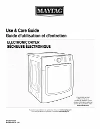 Maytag MED8200FC0
User Manual
Maytag MED8200FC0
User Manual
 Maytag MHW3505FW0
User Manual
Maytag MHW3505FW0
User Manual
 Maytag MGR8800DS0
User Manual
Maytag MGR8800DS0
User Manual
 Maytag MEDB880BW0
User Manual
Maytag MEDB880BW0
User Manual
 Maytag MEDX700XW0
User Manual
Maytag MEDX700XW0
User Manual
 Maytag MMV1174DS3
Installation Manual
Maytag MMV1174DS3
Installation Manual
 Maytag MVWX500XW2
User Manual
Maytag MVWX500XW2
User Manual
 Maytag MBF2258XEW6
User Manual
Maytag MBF2258XEW6
User Manual
 Maytag MVWC555DW0
User Manual
Maytag MVWC555DW0
User Manual
 Maytag MDB4949SDH2
User Manual
Maytag MDB4949SDH2
User Manual