Makita XRF03Z - Manuals
User Manual Makita XRF03Z


Summary
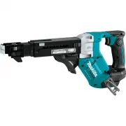
2 ENGLISH ENGLISH (Original instructions) SPECIFICATIONS Model: XRF03 Screw strip ø3.5 mm x 25 mm - ø4.2 mm x 55 mm (ø1/8″ x 1″ - ø5/32″ x 2-3/16″) No load speed (RPM) 0 - 6,000 /min Overall length 396 mm (15-5/8″) Rated voltage D.C. 18 V Net weight 1.9 - 2.2 kg (4.2 - 4.9 lbs) • Due to our continui...
4 ENGLISH Cordless screwdriver safety warnings 1. Hold the power tool by insulated gripping surfaces, when performing an operation where the fastener may contact hidden wiring. Fasteners contacting a "live" wire may make exposed metal parts of the power tool "live" and could give the...
5 ENGLISH Tips for maintaining maximum battery life 1. Charge the battery cartridge before completely discharged. Always stop tool operation and charge the battery cartridge when you notice less tool power. 2. Never recharge a fully charged battery cartridge. Overcharging shortens the battery servic...
Makita Impact Drivers Manuals
-
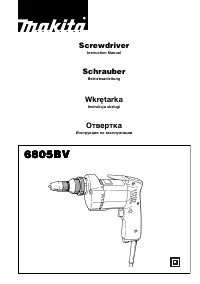 Makita 6805BV
User Manual
Makita 6805BV
User Manual
-
Makita 6805BV
Manual
-
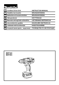 Makita BDF453SHE
User Manual
Makita BDF453SHE
User Manual
-
 Makita BTP141Z
User Manual
Makita BTP141Z
User Manual
-
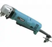 Makita DA3010F
User Manual
Makita DA3010F
User Manual
-
Makita DA3010F
Manual
-
 Makita DA3011F
User Manual
Makita DA3011F
User Manual
-
Makita DA3011F
Manual
-
 Makita DDA351Z
User Manual
Makita DDA351Z
User Manual
-
 Makita DDA450ZK
User Manual
Makita DDA450ZK
User Manual
-
 Makita DDA460Z
User Manual
Makita DDA460Z
User Manual
-
 Makita DDF451RFE
User Manual
Makita DDF451RFE
User Manual
-
 Makita DDF453SYX4
User Manual
Makita DDF453SYX4
User Manual
-
 Makita DDF484RAE
User Manual
Makita DDF484RAE
User Manual
-
 Makita DDF484RME
User Manual
Makita DDF484RME
User Manual
-
 Makita DDF484Z
User Manual
Makita DDF484Z
User Manual
-
 Makita DDF485FYX3
User Manual
Makita DDF485FYX3
User Manual
-
 Makita DDF485RFJ
User Manual
Makita DDF485RFJ
User Manual
-
 Makita DDF486Z
User Manual
Makita DDF486Z
User Manual
-
 Makita DF001GD201
User Manual
Makita DF001GD201
User Manual