Liebherr UKES1752RH - Manuals
User Manual Liebherr UKES1752RH


Summary
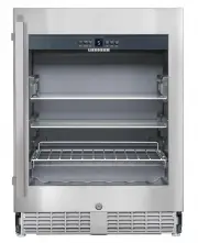
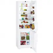
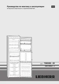
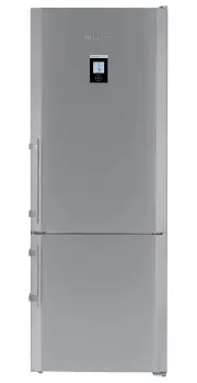
2 Operating and control ele- ments Type plate Interior light (LED light strip) Pull-out grid shelf Dust filter Adjustable glass shelf Sectioned glass shelf Disposal notes The appliance contains reusable materials and should be disposed of properly - not simply with unsorted household refuse. Applian...
3 Safety instructions and warnings • To prevent injury or damage to the unit, the ap - pliance should be unpacked and set up by two people. • In the event that the appliance is damaged on delivery, contact the supplier immediately before connecting to the mains. • To guarantee safe operation, ensure...
4 Setting up • Avoid positioning the appliance in direct sunlight or near cookers, radiators and similar sources of heat. • Standard EN 378 specifies that the room in which you install your appliance must have a volume of 1 m 3 per 8 g of R 600a refriger- ant used in the appliance, so as to avoid th...
Liebherr Refrigerators Manuals
-
 Liebherr B 2756
User Manual
Liebherr B 2756
User Manual
-
 Liebherr B 2756 Premium BioFresh
User Manual
Liebherr B 2756 Premium BioFresh
User Manual
-
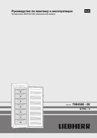
 Liebherr BNes_SBNes ... 6
User Manual
Liebherr BNes_SBNes ... 6
User Manual
-
 Liebherr C 4023
User Manual
Liebherr C 4023
User Manual
-
 Liebherr C5740IM
User Manual
Liebherr C5740IM
User Manual
-
 Liebherr CBesf 4006 BioFresh
User Manual
Liebherr CBesf 4006 BioFresh
User Manual
-
 Liebherr CBN 3656
User Manual
Liebherr CBN 3656
User Manual
-
 Liebherr CBN 3656 Premium
User Manual
Liebherr CBN 3656 Premium
User Manual
-
 Liebherr CBN 3913 Comfort
User Manual
Liebherr CBN 3913 Comfort
User Manual
-
 Liebherr CBN 3956 Premium
User Manual
Liebherr CBN 3956 Premium
User Manual
-
 Liebherr CBNb 3913
User Manual
Liebherr CBNb 3913
User Manual
-
 Liebherr CBNb 3913 Comfort
User Manual
Liebherr CBNb 3913 Comfort
User Manual
-
 Liebherr CBNes 3656
User Manual
Liebherr CBNes 3656
User Manual
-
 Liebherr CBNes 3656 Premium
User Manual
Liebherr CBNes 3656 Premium
User Manual
-
 Liebherr CBNes 3956 Premium
User Manual
Liebherr CBNes 3956 Premium
User Manual
-
 Liebherr CBNes 3957
User Manual
Liebherr CBNes 3957
User Manual
-
 Liebherr CBNes 3957 Premium
User Manual
Liebherr CBNes 3957 Premium
User Manual
-
 Liebherr CBNes 5167
User Manual
Liebherr CBNes 5167
User Manual
-
 Liebherr CBNes 6256 PremiumPlus
User Manual
Liebherr CBNes 6256 PremiumPlus
User Manual
-
 Liebherr CBNES5167RH
User Manual
Liebherr CBNES5167RH
User Manual