Page 2 - Danger of suffocation due to packing material; Description of the appliance; Installation instructions; Noise emissions from the appliance; Important
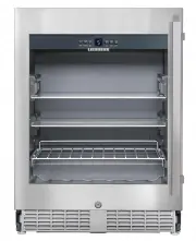
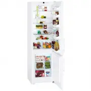
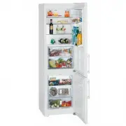
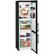
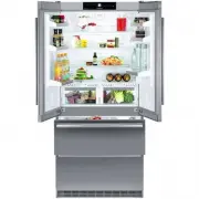
2 Operating and control elements Type plate Interior light (LED light strip) Pull-out grid shelf Dust filter Adjustable glass shelf Sectioned glass shelf Disposal notes The appliance contains reusable materials and should be disposed of properly - not simply with unsorted household refuse. Appliance...
Page 4 - Setting up; • Standard EN 378 specifies that the room in; Do not cover ventilation openings; Switching the appliance on and off; Switching the appliance on; Operating and control elements; The socket must not be situated behind the appli-; Child lock activated symbol; Climate rating; The minimum room temperature at the place of installation is 10°C.; Range of appliance use; The appliance is suited only for cooling food.; and products subject to the Medical Devices Directive 2007/47/EC.; Appliance dimensions; Width
4 Setting up • Avoid positioning the appliance in direct sunlight or near cookers, radiators and similar sources of heat. • Standard EN 378 specifies that the room in which you install your appliance must have a volume of 1 m 3 per 8 g of R 600a refriger- ant used in the appliance, so as to avoid th...
Page 5 - Temperature alarm after a fault in the appliance; Interior light; Locking the appliance
5 EN Setting the temperature Increasing the temperature Press the Up button. Reducing the temperature Press the Down button. - When pressing one of the buttons for the first time, the display will start to flash. - Pressing this button again enables you to change the temperature setting. - The elect...
Page 6 - Setup mode; from being switched off accidentally.; Activating the child lock; Note
6 Setup mode In setup mode you can set the child lock and adjust the brightness of the display. The child lock is designed to protect the appliance from being switched off accidentally. Activating the child lock Press for 5 seconds. Display = Display = Display = Display = Display = Deactivating the ...
Page 7 - Equipment; Sectioned glass shelf; front half; IMPORTANT
7 EN Pull-out shelf The pull-out shelf allows bot- tles or cans to be viewed and removed more easily. Equipment Sectioned glass shelf If you need to make space for tall containers, simply carefully slide the front half of the sectioned glass shelf underneath the back half. IMPORTANT 1 The sectioned ...
Page 8 - Cleaning; Clean the appliance at least twice per year.; Do not use steam cleaners because of the; Cleaning the dust filter; Do not; Cleaning the appliance interior
8 Cleaning Clean the appliance at least twice per year. Before cleaning, always switch off the appliance. Disconnect from the mains or switch off or unscrew the fuse. • Clean the inside and outer walls with lukewarm water and a lit - tle detergent. Do not use abrasive or acid cleaners or chemical so...
Page 9 - Malfunctions; – The appliance has suffered a fault. Contact the customer service; The fans inside the appliance are running although the; – Demo mode is activated. Contact the customer service depart; Shutting your appliance down; it off and disconnect the plug or switch off or unscrew the fuse.
9 EN Malfunctions • F1 appears in the display. – The appliance has suffered a fault. Contact the customer service department. • The fans inside the appliance are running although the fan function has been deactivated and the compressor (refrigeration unit) is idle. – This is a normal operating state...
Page 10 - Mounting the dust filter; Remove the protective film from the; at the bottom; Appliance venting; The required air flow is directed through; Cut-out section in the plinth panel; Supplied accessories; Cover strips; The cut-out section in the
10 Mounting the dust filter The supplied dust filter prevents that dirt enters the motor compartment, reducing the refrigeration performance. Therefore always install the dust filter. Remove the protective film from the dust filter. Insert the filter at the bottom and click into place at the top . A...
Page 11 - Installation dimensions; View from
11 EN Appliance dimensions 1 In this area, the power cord comes out of the appliance rear. Free length of the power cord = 2000 mm Choose the position of the socket considering these specifications. The socket must not be situated behind the appli- ance and must be easily accessible. Installation di...
Page 12 - Installing the appliance; The appliance must be aligned horizontally and verti-; When sliding in the appliance, make sure that the mains; • Screw the appliance to the
12 4. 2. 3. Installing the appliance 2 . Adjust the height of the appliance to 4 mm less than the recess height by turning the adjustable feet clockwise. Turn the spanner anticlockwise to raise the appliance front and clockwise to lower it. Position the spanner accordingly Important The appliance mu...
Page 13 - If the foam moulding is not installed, the appliance will not; backwards into its final position.; The foam moulding must be touching the ventilation grille.
13 EN 5. 6. 7. 8. 7. Insert the ventilation grille in the plinth panel. 5. Screw the appliance to the body of the unit at the bottom on the left and right. 6. Insert the foam moulding ap- prox. 10 mm into the opening in the appliance plinth as in- dicated. Important If the foam moulding is not insta...
Page 14 - Changing over door hinges; Changing the door hinges must be done by two people.
14 Changing over door hinges Door hinges should only be changed by a trained expert. Changing the door hinges must be done by two people. 1. 2. 3. 4. 5. 1. Remove screw. 2. Remove screw. Important The door must now be held secure by somebody. 3. Pull out hinge pin. 4. Remove upper hinge pin. 5. Move...
Page 16 - Insert the hinge pin with the flat part
16 19. 19. Fit the door on the hinge brackets. Important The door must now be held secure by somebody. 20. Insert hinge pin. The door must be open 90°. Insert the hinge pin with the flat part facing the appliance.The hinge pin must be full inserted in the borehole and must not protrude at the top. 2...
Page 17 - Close door and check that it; Adjusting the lateral tilt of the door
17 EN 24. 22. 25. 23. Close door and check that it is aligned with the side walls of the appliance. Adjusting the lateral tilt of the door If the door is at an angle, adjust the angle. 24. Undo screws and slide hinge bracket to the right or left. Tighten screws. 21. Insert the bottom hinge pin in th...
Page 20 - Liebherr Hausgeräte Lienz GmbH; Österreich
Liebherr Hausgeräte Lienz GmbH Dr.-Hans-Liebherr-Strasse 1 A-9900 Lienz Österreich www.liebherr.com *708023201*