Liebherr SICN3056RH - Manuals
User Manual Liebherr SICN3056RH


Summary
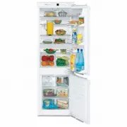
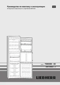
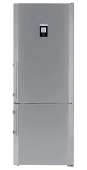
14 Operating and control panel , Figure A1 Freezer section 1 Alarm off button for audible warning signal 2 SuperFrost button with light emitting diode (LED) display, when lit = it is switched on 3 Appliance main on/off switch 4 Temperature setting buttons: left hand button = warmer, right-hand butto...
15 GB Keep these user instructions in a safe place and, if appropriate, hand them to the next owner of the appliance. The instructions apply to several models, so may vary slightly. Conditions • The appliance is intended for use to cool, freeze and store food, and to make ice. It is designed for hou...
16 Connection Electric current (alternating current) and voltage The information on the type plate must conform with the location. The type plate is located inside the appliance on the left, fig. A . • The appliance must be connected using a properly installed shock-proof plug. • The plug must be fu...
Liebherr Refrigerators Manuals
-
 Liebherr B 2756
User Manual
Liebherr B 2756
User Manual
-
 Liebherr B 2756 Premium BioFresh
User Manual
Liebherr B 2756 Premium BioFresh
User Manual
-
 Liebherr BNes_SBNes ... 6
User Manual
Liebherr BNes_SBNes ... 6
User Manual
-
 Liebherr C 4023
User Manual
Liebherr C 4023
User Manual
-
 Liebherr C5740IM
User Manual
Liebherr C5740IM
User Manual
-
 Liebherr CBesf 4006 BioFresh
User Manual
Liebherr CBesf 4006 BioFresh
User Manual
-
 Liebherr CBN 3656
User Manual
Liebherr CBN 3656
User Manual
-
 Liebherr CBN 3656 Premium
User Manual
Liebherr CBN 3656 Premium
User Manual
-
 Liebherr CBN 3913 Comfort
User Manual
Liebherr CBN 3913 Comfort
User Manual
-
 Liebherr CBN 3956 Premium
User Manual
Liebherr CBN 3956 Premium
User Manual
-
 Liebherr CBNb 3913
User Manual
Liebherr CBNb 3913
User Manual
-
 Liebherr CBNb 3913 Comfort
User Manual
Liebherr CBNb 3913 Comfort
User Manual
-
 Liebherr CBNes 3656
User Manual
Liebherr CBNes 3656
User Manual
-
 Liebherr CBNes 3656 Premium
User Manual
Liebherr CBNes 3656 Premium
User Manual
-
 Liebherr CBNes 3956 Premium
User Manual
Liebherr CBNes 3956 Premium
User Manual
-
 Liebherr CBNes 3957
User Manual
Liebherr CBNes 3957
User Manual
-
 Liebherr CBNes 3957 Premium
User Manual
Liebherr CBNes 3957 Premium
User Manual
-
 Liebherr CBNes 5167
User Manual
Liebherr CBNes 5167
User Manual
-
 Liebherr CBNes 6256 PremiumPlus
User Manual
Liebherr CBNes 6256 PremiumPlus
User Manual
-
 Liebherr CBNES5167RH
User Manual
Liebherr CBNES5167RH
User Manual