Page 2 - THIS APPLIANCE HAS BEEN DESIGNED FOR DOMESTIC USE ONLY; CONTENTS
2 READ THE INSTRUCTION BOOKLET BEFORE INSTALLING AND USING THE APPLIANCE. It is important that you retain these instructions, proof of purchase as well as other important documents about this product for future reference. The manufacturer will not be responsible for any damage to property or to pers...
Page 4 - LOCAL AUTHORITY REQUIREMENTS; withstand a minimum temperature of 65°; Clearance above and around domestic cookers; REQUIREMENTS
4 LOCAL AUTHORITY REQUIREMENTS Before installation, unpack all parts from carton, remove all internal packaging and transit protection where present and check for damage. Check Gas Type and specifications plate placed on the rear of the unit, alternatively there is a second label supplied. All gas f...
Page 5 - APPLIANCE SERVICING
5 IMPORTANT INFORMATION FOR INSTALLING AND SERVICING THE APPLIANCE The cooker can be installed separately, as a freestanding unit, or between kitchen units or between a kitchen unit and the wall. This appliance is not connected to devices which exhaust combustion products. Special attention must be ...
Page 6 - sure that the gas passage ways are unobstructed.; Location and Aeration
6 Light one burner at a time and set the knob to the MINIMUM position (small flame). Remove the knob. The range is equipped with a safety valve. Using a small-size slotted screwdriver, locate the choke valve on the valve body and turn the choke screw to the right or left until the burner flame is ad...
Page 7 - APPLIANCE GAS CONNECTION; This appliance must be installed by an authorised person.; flexible hose; , a supplemental hose nipple fitting is needed which is; Gas inlet positions with different leg heights – mm; Gas Regulator; flame to check for gas leaks.; Using a flexible connection; Using a Copper Pipe connection; The valve must be easily accessible at all times.
7 APPLIANCE GAS CONNECTION IMPORTANT: This appliance must be installed by an authorised person. WARNING: DO NOT MODIFY THIS APPLIANCE If the appliance cannot be adjusted to perform correctly, contact the service department. This appliance utilises a threaded 1/2" gas male fitting. To connect the...
Page 8 - Adaption to various types of gas; Burners Gas; Test the operation of the cooker before leaving; SUPPORT LEGS AND BACKGUARD INSTALLATION
8 TABLE N°1 Adaption to various types of gas Burners Gas type Pressure (kPa) Injector (mm) Mj/hr By-pass size (mm) Small Natural 1.00 0.90 4.00 0.30 regulated Small ULPG 2.75 0.54 4.00 0.30 Medium Natural 1.00 1.18 7.00 0.36 regulated Medium ULPG 2.75 0.70 7.00 0.36 Large Natural 1.00 1.55 11.50 0.5...
Page 9 - TAKE CARE DO NOT OBSTRUCT THE OUTLET
9 Fig. 08 Legs should be installed with the appliance close to its final destination, as the legs are not designed for excessive force and will snap off if too much side force is exerted on them (dragging along or angled too much). When fitting, try to keep the appliance as close to a horizontal pos...
Page 10 - ANTI-TILT DEVICE AND STRAIN RELIEF FLEXIBLE HOSE DEVICE; ANTI-TILTING CHAIN/HOSE RESTRAINING CHAIN
10 ANTI-TILT DEVICE AND STRAIN RELIEF FLEXIBLE HOSE DEVICE ANTI-TILTING CHAIN/HOSE RESTRAINING CHAIN A chain must be fitted by the installer within 50mm of the hose connection point to prevent strain on the hose when the cooker is pulled forward. The chain should restrict the appliance movement to n...
Page 11 - Left Side
11 Left Side In order to prevent the oven from tipping forward as shown on the previous page, we need to make sure both chains provided with the oven are used. On the left side of the oven a 16mm drill bit was used to drill through the cabinetry into the adjacent cabinet, as you can see the hole has...
Page 12 - WARNING; CONVERSION TO DIFFERENT TYPES OF GAS; REPLACING THE NOZZLES TO OPERATE WITH ANOTHER TYPE OF GAS; If converting to Natural Gas, fit gas regulator
12 WARNING : In order to prevent accidental tipping of the appliance, for example a child climbing onto the open oven door, the stabilising means must be installed. Ensure the chains are correctly anchored to prevent the appliance from tilting forward and to prevent strain on the hose when the cooke...
Page 13 - : follow the instructions below to adjust the minimum:; Fig. 13 Fig.14 Fig.15
13 4) Unscrew the nozzles using a 7 mm spanner, and replace them (Fig.12) with those needed for the new type of gas according to what is indicated in the Energy Consumption Table. Fig.12 5) Burner "MINIMUM" adjustment: Work surface burner adjustment : follow the instructions below to adjust ...
Page 14 - APPLIANCE ELECTRICAL CONNECTION; Range with Multifunction Electric oven :
14 APPLIANCE ELECTRICAL CONNECTION The electric connection must comply with the current legal standards and regulations. Before making the connection, check that: • The system electrical rating and the current outlet are adequate for the maximum power output of the appliance (see the label applied t...
Page 15 - INSTALLATION CHECKLIST; FINAL PREPARATION
15 INSTALLATION CHECKLIST 1. Is the range mounted on its legs? 2. Is the backguard securely connected? 3. Has the anti-tip device been properly installed? 4. Does the clearance from the side cabinets comply with the manufacturers directions? 5. Is the electricity properly grounded? 6. Is the gas ser...
Page 16 - APPLIANCE USE AND MAINTENANCE; ATTENTION: TAKE CARE DO NOT; along the support base.; Please maintain your; REPLACING PARTS
16 APPLIANCE USE AND MAINTENANCE ATTENTION: Important Warnings. ATTENTION: ATTENTION: TAKE CARE DO NOT OBSTRUCT THE OUTLET OPENINGS ON THE BACKGUARD; THEY MUST BE UNOBSTRUCTED FOR PROPER OPERATION • For cookers resting on base ATTENTION : if the cooker rest on a base, take the measures necessary to ...
Page 17 - CONTROL PANEL DESCRIPTION; OVEN RACKS AND TRAYS
17 WARNING: Before replacing the bulb, disconnect the appliance from the electric power supply. WARNING : The power cord supplied with the appliance is connected to the appliance with an X type connection (in compliance with standards AS/NZS 60335-1, AS/NZS 60335-2-6 and subsequent amendments) for w...
Page 18 - Tips for using burners correctly:
18 this position until the burner ignites, and then wait 2 seconds for the thermocouple to heat up. Release the control knob and adjust to the correct setting. Fig. 18 -Use of the dual burner (Fig19) This model controls both the central and external crown of the burner with just one valve. To igni...
Page 19 - USING THE GAS OVEN; relight the oven until after at least 1 minute.; The oven burner can be ignited in different ways:
19 USING THE GAS OVEN GAS OVEN: All the gas oven cookers are equipped with a thermostat and safety device to adjust the cooking temperature. The oven temperature is set by turning the knob counterclockwise to match the indicator with the temperature selected. The gas oven can be combined with a gas ...
Page 21 - USING THE OVEN THERMOSTAT CONTROL KNOB
21 USING THE OVEN THERMOSTAT CONTROL KNOB The thermostat is used to set the maximum internal temperature of the oven. Turn the thermostat control knob clockwise and align the selected temperature indicated on the knob with the index etched on the control panel above it. Thermostat operation is indic...
Page 22 - FAN ASSIST COOKING FUNCTION; : This function runs the upper and lower elements, and; FAN OVEN COOKING FUNCTION; : This function runs the circular rear elements and; PIZZA COOKING FUNCTION; : This function runs the lower and circular rear elements, and; USING THE ELECTRIC OVEN; conventional cooking; After preheating oven to the correct temperature (50; fan oven cooking
22 used for longer grilling times, or when grilling foods with a lot of moisture. FAN ASSIST COOKING FUNCTION : This function runs the upper and lower elements, and runs both rear internal fans. It is dependent on the timer and the thermostat setting. Best used when cooking large amounts of food at ...
Page 23 - USING THE END OF COOKING TIMER (fig 25) Fig 24; NOTE; : This function is available for the electric oven only.; USING THE DIGITAL CLOCK (fig.26); Power on; Display is flashing; Time of day function; minutes in the long time section.
23 minutes before inserting the trays. Adjust oven function control knob to fan oven cooking and place food inside oven. Set timer if needed. grilling The grill is controlled using the oven’s temperature knob. The grill function uses both elements at the top of the oven, so is faster and more powerf...
Page 24 - USING THE TOUCH CLOCK; Mains frequency detection; is cancelled.; The Buzzer; First; Clearing Programs and Manual function; ic; Key Lock
24 The maximum time is 10 h. The format change will happen after 99 minutes and 50 seconds to 1 hour and 40 minutes. The pot- symbol illuminated. To show time of day press “time of day” button for 6 seconds. Reset timer Count down to zero with permanent pressing “ – “ button. (automatic stop at zero...
Page 25 - USING THE ANALOG CLOCK; getting the CLOCK icon flashing.; USING THE ELECTRONIC TIMER
25 USING THE ANALOG CLOCK (fig.28) For setting up the time displayed by watch pointers push briefly twice the knob till getting the CLOCK icon flashing. For increasing or decreasing time displayed 1 minute by 1, turn the knob clockwise or counterclockwise, le minutes pointer will increase or decreas...
Page 26 - any point by pressing the appropriate function button.; Cancelling timer functions; USING THE; The first start up; Timer
26 When the start time is reached (end time – duration), the cook pot symbol appears again and the oven becomes active. When the end time has been reached, the oven and the cook pot symbol are turned off. An audible signal sounds and the symbol “A” will begin to flash. Reset the oven to off using th...
Page 27 - End of cooking; wi
27 10h) . The selected time is automatically processed by the programmer in a few seconds, or you can also touch the M key many times just to see again the current time . The A and (2) symbols will be on the display . Once the set cooking time is finished, a sound will be heard and the oven automati...
Page 28 - USING THE THERMOMETER; temperatures more accurately.; USING; and dried before being replaced.
28 USING THE THERMOMETER (fig.31) The cooker is fitted with a device to measure the temperature in the middle of the oven. This lets you check the temperature inside the oven and adjust food cooking temperatures more accurately. Electric oven When you turn on the oven, the orange light comes on to i...
Page 30 - DISPOSAL INFORMATION
30 TROUBLESHOOTING If you have a problem with your appliance, check the following before contacting service. PROBLEM SOLUTION Oven or hob not working Check the electricity is turned on. Check your fuses. If the fuse continues to blow, call Bertazzoni Group service. Check the circuit breaker. Ensure ...
Page 31 - BERTAZZONI AUSTRALIA Pty Ltd; APPLY WIRING DIAGRAM LABELS
31 BERTAZZONI AUSTRALIA Pty Ltd ABN 91 623 588 027 PO Box 5317 South Melbourne, Victoria 3205 Contact number 1800 65 42 65 Email: [email protected] APPLY WIRING DIAGRAM LABELS


 La Germania AMS96C61LBCR
User Manual
La Germania AMS96C61LBCR
User Manual
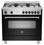
 La Germania AMS96C61LBNE
User Manual
La Germania AMS96C61LBNE
User Manual
 La Germania AMS96C61LBVI
User Manual
La Germania AMS96C61LBVI
User Manual
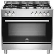
 La Germania AMS96C61LBX
User Manual
La Germania AMS96C61LBX
User Manual
 La Germania AMS96C71BCR
User Manual
La Germania AMS96C71BCR
User Manual
 La Germania AMS96C71BVI
User Manual
La Germania AMS96C71BVI
User Manual
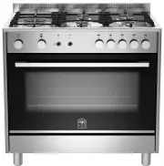
 La Germania AMS96C71BX
User Manual
La Germania AMS96C71BX
User Manual
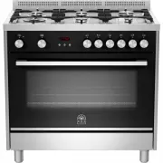
 La Germania AMS96C71LBNE
User Manual
La Germania AMS96C71LBNE
User Manual
 La Germania TUS95L61LDX
User Manual
La Germania TUS95L61LDX
User Manual
 La Germania TUS95L71DX
User Manual
La Germania TUS95L71DX
User Manual
 La Germania TUS96C61LBX
User Manual
La Germania TUS96C61LBX
User Manual
 La Germania TUS96C71BX
User Manual
La Germania TUS96C71BX
User Manual