KitchenAid KFED500ESS - Manuals
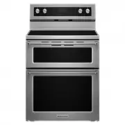
KitchenAid KFED500ESS Range – User Manual, Manual, Installation Manual in PDF format online.
Manuals:
User Manual KitchenAid KFED500ESS


Manual KitchenAid KFED500ESS


Installation Manual KitchenAid KFED500ESS


Summary
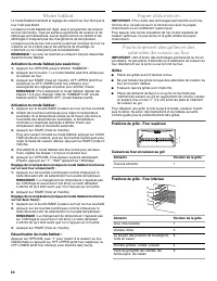
2 INSTALLATION REQUIREMENTS Tools and Parts Gather the required tools and parts before starting installation. Read and follow the instructions provided with any tools listed here. Tools Needed Parts Supplied Check that all parts are included. ■ 10-32 hex nuts (attached to terminal block) (3) ■ 3 - t...
3 Product Dimensions * Range can be raised approximately 1" (2.5 cm) by adjusting the leveling legs. ** Model/serial/rating plates may be rotated up from behind the control panel for viewing from the front of the range. ***Excludes handle. Dimension given is from wall to front of oven door and w...
4 Electrical Requirements If codes permit and a separate ground wire is used, it is recommended that a qualified electrical installer determine that the ground path and wire gauge are in accordance with local codes. Do not use an extension cord. Be sure that the electrical connection and wire size a...
KitchenAid Ranges Manuals
-
 KitchenAid KFDC500JAV
User Manual
KitchenAid KFDC500JAV
User Manual
-
KitchenAid KFDC500JAV
Manual
-
KitchenAid KFDC500JAV
Installation Manual
-
 KitchenAid KFDC500JBK
User Manual
KitchenAid KFDC500JBK
User Manual
-
KitchenAid KFDC500JBK
Manual
-
 KitchenAid KFDC500JIB
User Manual
KitchenAid KFDC500JIB
User Manual
-
KitchenAid KFDC500JIB
Manual
-
 KitchenAid KFDC500JMB
User Manual
KitchenAid KFDC500JMB
User Manual
-
KitchenAid KFDC500JMB
Manual
-
 KitchenAid KFDC500JMH
User Manual
KitchenAid KFDC500JMH
User Manual
-
KitchenAid KFDC500JMH
Manual
-
KitchenAid KFDC500JMH
Installation Manual
-
 KitchenAid KFDC500JPA
User Manual
KitchenAid KFDC500JPA
User Manual
-
KitchenAid KFDC500JPA
Manual
-
KitchenAid KFDC500JPA
Installation Manual
-
 KitchenAid KFDC500JSC
User Manual
KitchenAid KFDC500JSC
User Manual
-
KitchenAid KFDC500JSC
Manual
-
 KitchenAid KFDC500JSS
User Manual
KitchenAid KFDC500JSS
User Manual
-
KitchenAid KFDC500JSS
Installation Manual
-
KitchenAid KFDC500JSS
Manual