Page 4 - Table of contents; Section
4 2.0 Table of contents Section Page 1.0 IMPORTANT SAFETY INSTRUCTIONS ....................................................................................................... 2 2.0 Table of contents ......................................................................................................
Page 5 - About this manual
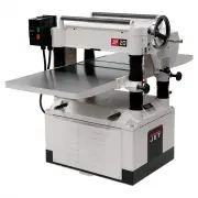
5 3.0 About this manual This manual is provided by JET, covering the safe operation and maintenance procedures for a JET Model JWP-15B and JWP-15BHH Planer. This manual contains instructions on installation, safety precautions, general operating procedures, maintenance instructions and parts breakdo...
Page 6 - Specifications
6 4.0 Specifications Table 1 Stock number 722150 722155 Model number JWP-15B JWP-15BHH Motor and Electricals Motor type Totally enclosed, fan-cooled, induction, capacitor start Horsepower 3 HP (2.2 kW) Phase Single Voltage 230 V only Cycle 60 Hz Listed FLA (full load amps) 11 A Start capacitor 300MF...
Page 8 - Setup and assembly; Shipping contents; Tools required for assembly
8 Read and understand all setup and assembly instructions before attempting to assemble the machine. Failure to comply may cause serious injury. IMPORTANT: If you purchased the helical head planer, before operating the machine verify that each knife insert has been properly torqued. Refer to sect. 7...
Page 9 - Handwheel
9 The planer should be operated in a well-lit area with good ventilation. Exposed metal surfaces, such as tables, rollers, cutterhead, etc., may have been given a protective coating at the factory. This can be removed with a soft cloth moistened with a good commercial solvent. Do not use acetone, ga...
Page 10 - Levelers; Electrical connections; GROUNDING INSTRUCTIONS; Extension cords
10 5.7 Levelers Check the planer for level by placing a bubble level on main table. If adjustment is needed, rotate any of the four leveling pads beneath the cabinet corners. Tighten the hex nuts up against the cabinet to secure the setting. 6.0 Electrical connections The JWP-15B and JWP-15BHH are p...
Page 11 - Adjustments; Belt tension/replacement
11 7.0 Adjustments 7.1 Belt tension/replacement Inspect belt tension frequently during the first few hours of operation, as new belts may stretch during this period. If the belt requires tightening, proceed as follows: 1. Disconnect planer from power source. 2. Remove side panel and belt guard. See ...
Page 12 - Replacing/rotating knife inserts; Operation; Start switch
12 11. Tighten all gib screws on the other two knives in the same fashion, until all gib screws on the cutterhead are firmly tightened. (NOTE: The purpose of this incremental tightening process is to prevent any slight deflection or warpage of the cutterhead, and to ensure that each knife is complet...
Page 14 - Outfeed roller height
14 NOTE: This procedure uses a home-made gauge block and feeler gauges, which should be sufficient for most planer operations. If more precise measurements are desired, use a dial indicator device. A home-made gauge block can be made out of hardwood. Figure 8-5 is an example. Figure 8-5 Figure 8-6 8...
Page 15 - Chip deflector; Maintenance; General maintenance; Gearbox
15 8.7.2 Infeed roller height Use the identical procedure for checking the infeed roller as you did for the outfeed roller. Use the 0.032" (0.81mm) feeler gauge atop the gauge block. If adjustment is necessary, use the lock nut and screw on each end of infeed roller. 8.7.3 Chipbreaker height The...
Page 16 - Fine adjustment
16 4. Reinstall drain plug (A) and fill gearbox with clean lubricant through hole (B). 5. Install and tighten filler cap (B). Figure 9-1 9.2 Belt replacement To replace the belt, remove cabinet panel and belt guard (see Figure 7-1). Rotate the pulleys using the belt, while gradually walking the belt...
Page 17 - Lubrication points
17 head casting; counterclockwise will decrease the distance. This adjustment is very sensitive and it should not be necessary to turn the sprocket more than one or two teeth. 7. When adjustments are correct, replace chain around corner sprocket, slide idler sprocket (S, Figure 9-3) back to re-tensi...
Page 18 - Performance problems
18 10.0 Troubleshooting JWP-15B,15BHH 10.1 Performance problems Table 4 Symptom Possible Cause Correction Snipe Inadequate support of long boards. Support long boards with an assistant or extension rollers. Uneven feed roller pressure front to back. Adjust feed roller pressure. Dull knives or knife ...
Page 19 - Mechanical and electrical problems
19 10.2 Mechanical and electrical problems Table 5 Symptom Possible Cause Correction * Uneven depth of cut side to side. Knife projection from cutterhead is incorrect (15B only). Adjust knife projection. Table not parallel to cutterhead. Adjust table/cutterhead parallelism. Board thickness does not ...
Page 20 - Replacement Parts
20 Symptom Possible Cause Correction * Machine will not start/restart or repeatedly trips circuit breaker or blows fuses. (cont.) Motor starter failure. Examine motor starter for burned or failed components. If damage is found, replace motor starter. If motor starter looks okay but is still suspect,...
Page 21 - Head Assembly – Exploded View
Page 22 - Head Assembly – Parts List; Index No Part No
22 11.1.2 Head Assembly – Parts List Index No Part No Description Size Qty 1 ................ JWP15B-101 ............. Head ........................................................................ ...................................... 1 2 ................ JWP15B-102 ............. Shaft ...............
Page 23 - Column Assembly – Exploded View
Page 24 - Column Assembly – Parts List
24 11.2.2 Column Assembly – Parts List Index No Part No Description Size Qty 1 ................ JWP15H-207 ............. Nut ........................................................................... ...................................... 4 2 ................ TS-1490081 .............. Hex Cap Screw...
Page 26 - Gear Box Assembly – Exploded View
Page 27 - Gear Box Assembly – Parts List
27 11.4.2 Gear Box Assembly – Parts List Index No Part No Description Size Qty 1 ................ JWP15B-401 ............. Gear Box Cover ....................................................... ...................................... 1 2 ................ TS-2246122 .............. Socket Head Button S...
Page 28 - Cabinet Assembly – Exploded View
Page 29 - Cabinet Assembly – Parts List
29 11.5.2 Cabinet Assembly – Parts List Index No Part No Description Size Qty 1 ................ TS-1550041 .............. Flat Washer ............................................................. M6 ................................. 4 2 ................ TS-2246122 .............. Socket Head Button ...
Page 32 - Electrical Connections for JWP-15B,15BHH
Page 33 - Warranty and service
33 13.0 Warranty and service JET warrants every product it sells against manufacturers’ defects. If one of our tools needs service or repair, please contact Technical Service by calling 1-800-274-6846, 8AM to 5PM CST, Monday through Friday. Warranty Period The general warranty lasts for the time per...