Page 2 - Warranty and Service
2 1.0 Warranty and Service JET warrants every product it sells against manufacturers’ defects. If one of our tools needs service or repair, please contact Technical Service by calling 1-800-274-6846, 8AM to 5PM CST, Monday through Friday. Warranty Period The general warranty lasts for the time perio...
Page 3 - Table of Contents; Section
3 2.0 Table of Contents Section Page 1.0 Warranty and Service ..................................................................................................................................... 2 2.0 Table of Contents ...................................................................................
Page 4 - Safety Warnings
4 3.0 Safety Warnings 1. Read and understand the entire owner's manual before attempting assembly or operation. 2. Read and understand the warnings posted on the machine and in this manual. Failure to comply with all of these warnings may cause serious injury. 3. Replace the warning labels if they b...
Page 6 - Specifications; assembly or operation! Failure to comply may cause serious injury!
6 Familiarize yourself with the following safety notices used in this manual: This means that if precautions are not heeded, it may result in minor injury and/or possible machine damage. This means that if precautions are not heeded, it may result in serious injury or possibly even death. 4.0 Specif...
Page 7 - Features and Terminology; Receiving; Use care when cleaning the; Unpacking; Contents of Shipping Container; Electrical Connection; All electrical connections
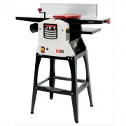
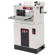
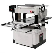
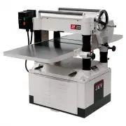
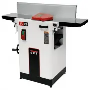
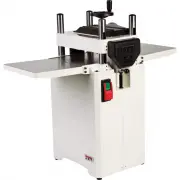
7 5.0 Features and Terminology Figure 1 6.0 Receiving Carefully unpack the machine and any loose items from the wood case and inspect for damage. Any damage should be reported immediately to your distributor and shipping agent. Before proceeding further, read your manual thoroughly to familiarize yo...
Page 8 - Operating Controls; Jointer to Planer Setup
8 9.0 Operating Controls Disconnect machine from power source before making any adjustments. Failure to comply may cause serious injury. Cutterhead knives are dangerously sharp. Use extreme caution when working around them. Failure to comply may cause serious injury. 9.1 Jointer to Planer Setup Refe...
Page 9 - Planer must be running when; Jointer Controls and
9 9.3 Control Switch Refer to Figure 4: Press the green switch to start. Press the red switch to stop. To prevent unauthorized or accidental starting of the machine, remove the safety key from the green switch and store in a safe place. The key must be reinserted to start the machine. Figure 4 9.4 P...
Page 10 - Adjustments; Fence Stop Adjustments; Note
10 Figure 7 Cutterhead Guard Refer to Figure 8: Properly positioned, the cutterhead guard (B) should rest against the fence (A). Fence Movement Refer to Figure 8: The fence (A) can be moved forward (C) or backward (D) across half the width (W) of the table, with 6" travel. It also tilts up to 45...
Page 11 - Table and Knife Adjustments
11 5. If the fence (A) is not square to the table, release the tilt locking handle (G), loosen the lock nut (B), and turn the stop bolt (C) until the fence is square to the table. 6. Tighten the lock nut (B) to retain the setting. Tighten the tilt locking handle (G). 45° Backward Stop Fence Adjustme...
Page 15 - Replacing Cutterhead Knives
15 For best results, knives should be set at approximately .04" above the cutterhead. Knife height should not vary more than .002 - .003" across the length of the cutterhead. All three knives must be set at equal height in the cutterhead and parallel to the outfeed table across their length....
Page 17 - Belt Replacement
17 Figure 19 10.8 Belt Replacement Refer to Figures 20 - 22: Preparation To replace the cutterhead drive belt and/or the planer feed-roller belt , the jointer fence assembly and two back panels must first be removed as described below. A 4mm hex wrench, 5mm hex wrench, and 17mm open wrench are requi...
Page 19 - Planer Table Adjustment
19 10.11 Planer Table Adjustment Checking Planer Table Parallel to Cutterhead Refer to Figures 24 and 25: The planer table is set parallel to the cutterhead by the manufacturer and no further adjustment should be needed. If your machine is planing a taper, first check to see if the knives are proper...
Page 20 - Basic Operations; Dust Collection; DO NOT attempt to inves-; Changing Mode of Operation; Jointer Operations; Never pass hands directly
20 Figure 26 11.0 Basic Operations 11.1 Dust Collection Before initial operation, the machine must be connected to a dust collector. 11.2 Initial Startup After the assembly and adjustments are complete, the planer is ready to be tested. Turn on the power supply at the main panel. Press the start but...
Page 21 - When workpiece is twice the
21 Direction of Grain Avoid feeding work into the jointer against the grain (Figure 29). This may result in chipped and splintered edges. Figure 29 Feed with the grain to obtain a smooth surface, as shown in Figure 30. Figure 30 Jointing Jointing (or edging) is the process of creating a finished, fl...
Page 22 - Planer Operations; Do not plane a board that is
22 Several passes may be required to achieve the full bevel. Figure 32 11.5 Planer Operations Depth of Cut Thickness planing refers to the sizing of lumber to a desired thickness while creating a level surface parallel to the opposite side of the board. The board thickness that the planer will produ...
Page 23 - To avoid the risk of injury due; Maintenance; Blade Care; Blades are extremely sharp!
23 Feeding the Work The planer is supplied with planer blades mounted in the cutterhead, and infeed and outfeed rollers adjusted to the correct height. The planer feed is automatic; it will vary slightly depending on the type of wood. Preparation: Feed rate refers to the rate at which the lumber t...
Page 24 - Sharpening the Knives (Straight; Lubrication
24 12.2 Sharpening the Knives (Straight Knives Only) Disconnect machine from power source before making any adjustments. Failure to comply may cause serious injury. Blades are extremely sharp! Use caution when handling. Failure to comply may cause serious injury! 1. Disconnect machine from power sou...
Page 25 - Trouble
25 14.0 Troubleshooting the JPJ-12B,JPJ-12BHH 14.1 Performance Troubleshooting – Jointer Trouble Probable Cause Remedy Finished stock is concave on back end. Knife is higher than outfeed table. Align cutterhead knives with outfeed table. See sect. 10.4, sect. 10.4, Setting Knives at Correct Height a...
Page 27 - Mechanical Troubleshooting; Replacement Parts
27 14.3 Mechanical Troubleshooting – Planer/Jointer Trouble Probable Cause Remedy Chain jumping. Inadequate tension. Adjust chain tension. Sprockets misaligned. Align sprockets. Sprockets worn. Replace sprockets. Machine will not start/ restart or repeatedly trips circuit breaker or blows fuses. No ...
Page 29 - Description
29 15.2 Infeed Table Assembly – Parts List Index No. Part No. Description Size Qty 1 ............... JPJ12B-101 ............. Fixed Jointer Table Hinge .................................... .................................... 1 2 ............... JPJ12B-102 ............. Socket Head Cap Screw w/threa...
Page 46 - Optional Accessories
46 17.0 Optional Accessories These items are purchased separately. Stock No. Description 708821 ............. Replacement Straight Knives for JPJ-12B Planer-Jointer (set of 3) 1791212 ........... Replacement Knife Inserts for JPJ-12BHH Planer-Jointer (set of 10) 709209 ............. Roller Stand, 12...