Page 2 - Warranty and Service
2 Warranty and Service JET warrants every product it sells against manufacturers’ defects. If one of our tools needs service or repair, please contact Technical Service by calling 1-800-274-6846, 8AM to 5PM CST, Monday through Friday. Warranty Period The general warranty lasts for the time period sp...
Page 3 - Table of Contents
3 Table of Contents Warranty and Service .............................................................................................................................. 2 Table of Contents .................................................................................................................
Page 5 - Safety Decals; Stand Mounting Holes
5 Your risk from these exposures v aries, depending on how often you do this type of work. To reduce your exposure to these chemicals, work in a well-ventilated area, and work with approv ed safety equipment, such as those dust masks that are specifically designed to filter out microscopic particles...
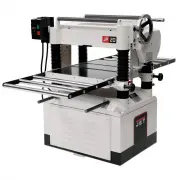
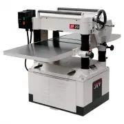
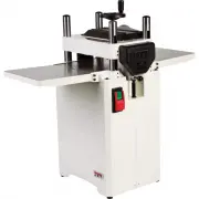
Page 6 - Features; Specifications
6 Features Figure 2 Specifications Model No. ............................................................................JWP-208 .................................... JWP-208HH Stock No (3HP, 1Ph, 230V only). ........................................... 708528 ............................................
Page 7 - Receiving; Use care when cleaning the; Installation & Assembly; Starter Box
7 Receiving Carefully unpack the planer and any loose items from the wood crate and inspect for damage. Any damage should be reported immediately to your distributor and shipping agent. Before proceeding further, read your manual thoroughly to familiarize yourself with proper assembly, maintenance a...
Page 8 - Handwheel; Dust Collection Hood
8 Handwheel 1. Remove the nut and washer from the gearbox shaft, and place the handwheel onto the shaft (Fig. 5), making sure it is oriented so the handwheel slips ov er the key. 2. Place flat washer and hex nut on shaft and tighten with wrench. 3. Mount the handle in the threaded hole in the handwh...
Page 9 - Electrical Connections; Electrical connections must be; Extension Cords; Adjustments; Belt and Pulleys
9 Electrical Connections Electrical connections must be made by a qualified electrician in compliance with all relevant codes. The machine must be properly grounded to help prevent electrical shock and possible fatal injury. A power plug is not provided with the 208 planer. You may either connect on...
Page 10 - Table Rollers; Overview
10 2. Check belt tension. Proper tension is obtained when there is approximately 1/4” deflection of the center span of the pulleys using light finger pressure (Fig. 10). 3. If adjustment of belt tension is necessary, loosen one pair of hex nuts (E & F, Fig. 11) and turn the other pair to raise o...
Page 11 - Adjusting Table Extension Rollers
11 Note: When raising the roller higher above the table, the available range is from .003” to .006” See Fig. 13. The table rollers are factory set for average planing and are parallel to the table surface. If you desire to adjust the table rollers higher or lower, proceed as follows: 1. Disconnect m...
Page 12 - Adjusting Depth of Cut; Always tighten the lock nuts; Cutterhead Adjustment
12 Adjusting Depth of Cut The cutting depth scale (A, Fig. 16) is a combination inch/metric scale with a cutting range from 0 to 8” (204mm). The distance of upward or downward mov ement is controlled by the handwheel (B, Fig. 16). One revolution of the handwheel is .059” (1.5mm). Before moving the t...
Page 13 - Note
13 NOTE: At this time, only tighten the knife in the slot just enough to hold knife in position. 6. If additional knives must be reset, repeat step 5. 7. After all four knives are set with screws just snug, back out and tighten the six locking screws (F, Fig. 19 & 20), against the slot starting ...
Page 14 - After replacing and checking
14 10. Replace and reset the other three kniv es in the same manner. 11. After all four knives are set with the screws just snug, back out and tighten the six screws (F) against the slot starting with the end screws first and then the center screws until the knife is securely held in the cutterhead....
Page 15 - Know the Transmitting Rollers of Your Planer
15 1. Disconnect machine from power source. 2. Place the gauge block (Figure 21) on the work table directly under the edge of a knife or knife insert as shown. Make slight contact with the knife edge by gently raising the table. 3. Mov e the gauge block to the opposite end of the work table. The dis...
Page 16 - Anti-Kickback Fingers
16 Anti-Kickback Fingers The anti-kickback fingers (A, Fig 23) help prev ent kickback of stock. They operate by gravity and it is necessary to inspect them occasionally to make sure they are free of gum and pitch, so that they move independently and operate correctly. Adjusting Infeed & Outfeed ...
Page 17 - Feed Speed Control; Return Rollers
17 4. Mov e the gauge block (J, Fig. 27) under one end of the outfeed roller (F, Fig. 27). The bottom of the outfeed roller should just touch the top of the gauge block. If an adjustment to the outfeed roller is necessary, loosen the lock nut (L, Fig 27) and turn screw (M, Fig. 27) until the outfeed...
Page 18 - Maintenance; Tip; Lubrication
18 Maintenance Periodic or regular inspections are required to ensure that the machine is in proper adjustment, that all screws are tight, that belts are in good condition, that dust has not accumulated in the electrical enclosures, and that there are no worn or loose electrical connections. Buildup...
Page 20 - Troubleshooting; Operating Problems
20 Troubleshooting Operating Problems Problem Possible Cause Solution Snipe. (Snipe cannot be eliminated, but can be minimized so as to become negligible.) Table rollers not set properly. Inadequate support of long boards. Unev en feed roller pressure front to back. Dull Kniv es. Lumber not butter p...
Page 22 - Optional Accessories; Ordering Replacement Parts; Head Assembly – Parts List
22 Problem Possible Cause Solution Miswiring of the unit. On/off switch failure. Double check to confirm all electrical connections are correct and tight. Refer to wiring diagrams on pages 32-35 to make any needed corrections. If the on/off switch is suspect you hav e two options: Hav e a qualified ...
Page 23 - Index Part
23 Head Assembly – Parts List Index Part No. Description Size Qty 25 ............. TS-1540041 .............Hex Nut ..............................................................M6 .............................. 8 26 ............. JWP208-026A ..........Key................................................
Page 25 - Head Assembly – Exploded View
Page 26 - Table and Roller – Parts and Assembly
26 Table and Roller – Parts and Assembly Index Part No. Description Size Qty 1 ............... JWP208HH-201 .......Middle Table .......................................................................................... 1 2 ............... 6292722...................Roller ...............................
Page 27 - Stand and Motor – Parts and Assembly
27 Stand and Motor – Parts and Assembly Index Part No. Description Size Qty 1 ............... JWP208-401 ............Stand .................................................................................................... 1 2 ............... JWP208-402 ............Cov er .............................
Page 28 - Base and Column – Parts List
28 Base and Column – Parts List Index Part No. Description Size Qty 1 ............... JWP208-301 ............Base ...................................................................................................... 1 2 ............... TS-1525021 .............Set Screw ................................
Page 29 - Base and Column – Assembly
Page 30 - Gearbox – Parts List
30 Gearbox – Parts List Index Part No. Description Size Qty 1 ............... JWP208-501 ............Gear Box ............................................................................................... 1 2 ............... OS-28408 ................Oil Seal ...........................................
Page 31 - Gearbox – Assembly
Page 32 - Wiring Diagrams
32 Wiring Diagrams 230V 3HP Single Phase A2 14NO 17 13NO O ManAuto 97 95 96 98 R R 4T2 6T3 2T1 3L2 5L3 1L1 A1