Page 2 - Warranty and Service
2 1.0 Warranty and Service Walter Meier (Manufacturing) Inc., warrants every product it sells. If one of our tools needs service or repair, one of our Authorized Service Centers located throughout the United States can give you quick service. In most cases, any of these W alter Meier Authorized Serv...
Page 3 - Table of contents; Section
3 2.0 Table of contents Section Page 1.0 Warranty and Service ..................................................................................................................................... 2 2.0 Table of contents .................................................................................
Page 4 - Safety warnings; Wear Eye Protection
4 3.0 Safety warnings For your own safety, read this instruction manual before operating the tool. Wear Eye Protection 1. KEEP GUARDS IN PLACE and in working order. 2. REMOVE ADJUSTING KEYS AND WRENCHES. Form the habit of checking to see that keys and adjusting wrenches are removed from the tool bef...
Page 5 - About this manual
5 18. NEVER STAND ON A TOOL. Serious injury could occur if the tool is tipped or if the cutting tool is unintentionally contacted. 19. CHECK DAMAGED PARTS. Before further use of the tool, a guard or other part that is damaged should be carefully checked to determine that it will operate properly and...
Page 6 - Electrical connections; Grounding instructions; 15 Volt operation; 30 Volt operation
6 5.0 Electrical connections 5.1 Grounding instructions In the event of a malfunction or breakdown, grounding provides a path of least resistance for electric current to reduce the risk of electric shock. This tool is equipped with an electric cord having an equipment-grounding conductor and a groun...
Page 7 - On-Off Switch Padlock
7 4. The planer/molder with a 230 volt plug should only be connected to an outlet having the same configuration as illustrated by the grounded outlet box in Figure 3. No adapter is available or should be used with the 230 volt plug. Important: In all cases (115 or 230 volts), make certain the recept...
Page 8 - Specifications
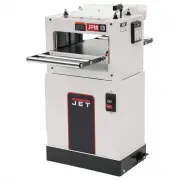
8 7.0 Specifications Model number ........................................................................................................................................ JPM-13CS Stock Number ..............................................................................................................
Page 9 - Glossary
9 8.0 Glossary • Cutterhead (A, Figure 5) – metal cylinder that holds the planer knives or the molding cutters. • Table – part of machine over which the lumber passes. • Feed Rollers – two rubber covered cylinders that push lumber through the machine. • Planer Knife – one of three knives found in th...
Page 10 - Setup and assembly; Shipping contents; Unpacking and cleanup; Adjustments: Planing; Depth of cut; Adjusting depth of cut scale
10 9.0 Setup and assembly 9.1 Shipping contents 1 Molder/Planer 1 Dust Chute 2 Extension Roller Assemblies 1 Accessory Package, containing: 1 Handle Assembly 1 10/12mm Wrench* 1 11/13mm Wrench* 1 Screwdriv er* 1 3mm Hex Wrench* 1 4mm T-Handle Hex Wrench* 1 5mm Hex Wrench* 1 Knife Setting Gauge* 1 Mo...
Page 11 - Feed rate adjustment; Adjusting V-Belt Tension
11 2. Measure the cut piece. 3. Adjust pointer accordingly. 10.3 Feed rate adjustment The planer/molder has two speeds that feed the work piece, at 10 feet per minute (FPM) for improved surface finish when molding and 20 FPM for faster planing. To change the feed rate gears: 1. Disconnect machine fr...
Page 12 - Knife replacement; Adjusting infeed roller and
12 12. Repeat steps five through eleven for blades two and three. 10.6 Knife replacement Use caution when placing hands near the cutterhead. Knives are extremely sharp. Failure to comply may cause serious injury. 1. Disconnect machine from power source. (Unplug) 2. Remove screws securing the dust ho...
Page 13 - Planing procedure; Dealing with warped wood
13 7. Insert the block labeled “Feed Roller Planing” into the planer opening. 8. Raise or lower the feed roller until it rests on top of the block end to end. To adjust the feed roller (Fig 12): • Loosen the jam nut on both sides of infeed roller with the wrench provided. • Turn the threaded bushing...
Page 14 - Wood Grain; Molding setup and; Installing molding cutters
14 Wood warped lengthwise - Feed rollers will flatten a lengthwise warped board as if it were flat, but the board will spring back to its original shape once out of the planer. A lengthwise warped board must be jointed flat on one side on a jointer before being thickness planed. Twisted wood - Twist...
Page 15 - Setting feed rollers for molding
15 • Install special lock bar that is included with the knife set. Make sure set screws are loose to allow locking adjustment. Do not tighten at this time. • Install cutter. Make sure it is facing proper direction and is fully seated in the cutterhead. 8. Install molding cutter gauge with hex socket...
Page 16 - Making & installing a bedboard; Making guide rails
16 12.3 Making & installing a bedboard You must use a board over the planer/molder table when molding. This prevents the knives from hitting the table and allows the knives to cut into the guide boards to clean up the sides of the molding. 1. Disconnect machine from power source (unplug). 2. Cut...
Page 17 - Molding procedure; Setting table height for first
17 8. Position second guide rail on the table. Placement of this rail depends on the width of the board and if the board requires outer edge clean-up. Review molding procedure section for pre-sizing stock guidelines. W hen using knives that require outer edge clean-up, the workpiece will contact the...
Page 18 - Back Relief Molding; Maintenance; Lubrication
18 12. Run all stock to be molded through the machine at this time. Note: If you are molding several boards with the same profile and have to make several passes to complete the profile, you must run all boards through at each setting. This assures all stock will match the desired shape. This is esp...
Page 19 - Troubleshooting the JPM-13CS; Mechanical and electrical problems
19 15.0 Troubleshooting the JPM-13CS 15.1 Mechanical and electrical problems Trouble Probable Cause Remedy Table difficult to adjust. Lack of lubrication on corner posts and screws. Lubricate corner posts and screws. Chain is jumping. Inadequate tension. Adjust chain tension. Sprockets misaligned. A...
Page 20 - Performance problems
20 15.2 Performance problems Trouble Probable Cause Remedy Snipe. Table rollers not set properly. Adjust rollers to proper height. Inadequate support of long boards. Support long boards with extension rollers. Uneven feed roller pressure front to back. Adjust feed roller pressure. Dull knives. Sharp...
Page 21 - Replacement Parts
21 16.0 Replacement Parts Replacement parts are listed on the following pages. To order parts or reach our service department, call 1-800-274-6848 Monday through Friday (see our website for business hours, www.waltermeier.com). Having the Model Number and Serial Number of your machine available when...
Page 22 - Table and Base Assembly – Exploded View
Page 23 - Table and Base Assembly – Parts List; Index
23 16.1.2 Table and Base Assembly – Parts List Index No Part No Description Size Qty 1 ................ MHA-B01W ............... Cover (left) ............................................................... ...................................... 1 2 ................ TS-0680021 ............
Page 26 - Gearbox Assembly – Parts List
Page 28 - Stand and Motor Assembly – Parts List
Page 30 - Electrical Connections