Page 3 - Contents; Preparing for installation ················································································· 1; Troubleshooting ···························································································· 19
i Contents Preparing for installation ················································································· 1 Safety recommendations ··································································································································· 1 Safety symbols ······...
Page 4 - Appendix B LEDs ·························································································· 25; Index ············································································································· 27
ii Appendix B LEDs ·························································································· 25 LEDs ································································································································································ 25 JH300A ···········...
Page 5 - Preparing for installation; Safety recommendations; Safety symbols
1 Preparing for installation The HPE MSR958 Router Series includes the models in Table 1 . Table 1 HPE MSR958 Router Series models Product code HPE description RMN JH300A HPE MSR958 1GbE and Combo Router BJNGA-BB0040 JH301A H PE MSR958 1GbE and Combo PoE Router BJNGA-BB0041 IMPORTANT: For regulatory...
Page 6 - ESD prevention; Examining the installation site; Temperature and humidity; Cleanliness
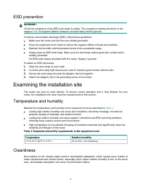
2 ESD prevention WARNING! Check the resistance of the ESD wrist strap for safety. The resistance reading should be in the range of 1 to 10 megohm (Mohm) between a human body and the ground. To prevent electrostatic discharge (ESD), follow these guidelines: • Make sure the router and the floor are re...
Page 7 - Cooling
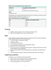
3 Table 3 Dust concentration limit in the equipment room Substance Concentration limit (particles/m 3 ) Dust particles ≤ 3 x 10 4 (No visible dust on the tabletop in three days) NOTE: Dust diameter ≥ 5 µm The equipment room must also meet strict limits on salts, acids, and sulfides to eliminate corr...
Page 8 - Installation accessories and tools
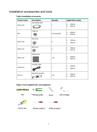
4 Installation accessories and tools Table 5 Installation accessories Product code Description Quantity Applicable models 5400-0125 Grounding cable 1 • JH300A • JH301A N/A Cage nut User-supplied • JH300A • JH301A 5400-0123 M6 screw 4 • JH300A • JH301A 5400-0124 M4 screw 4 • JH300A • JH301A 5400-0122...
Page 9 - Pre-installation checklist
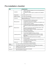
5 Pre-installation checklist Item Requirements Installation site Ventilation • There is a minimum clearance of 10 cm (3.9 in) around the air inlet and outlet vents. • An adequate ventilation system is available at the installation site. Temperature 0°C to 45°C (32°F to 113°F) Relative humidity 5% to...
Page 10 - Installing the router; Installation prerequisites; Installation flowchart
6 Installing the router WARNING! To avoid injury, do not touch bare wires, terminals, or parts with high-voltage hazard signs. IMPORTANT: • The barcode on the router chassis contains product information that must be provided to local sales agent when you return a faulty router for repair. • Keep the...
Page 11 - Mounting the router on a workbench
7 Figure 2 Installation flowchart Installing the router Mounting the router on a workbench IMPORTANT: • Make sure the workbench is clean, stable, and reliably grounded. • Maintain a minimum clearance of 10 cm (3.9 in) around the router for heat dissipation. • Do not place heavy objects on the router...
Page 12 - Installing the router in a rack
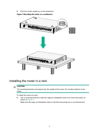
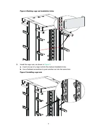
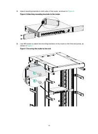
8 2. Place the router upside up on the workbench. Figure 3 Mounting the router on a workbench Installing the router in a rack CAUTION: The mounting brackets can support only the weight of the router. Do not place objects on the router. To install the router in a rack: 1. Use a mounting bracket to ma...
Page 15 - Grounding the router
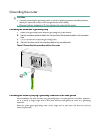
11 Grounding the router CAUTION: • Correctly connecting the grounding cable is crucial to lightning protection and EMI protection. When you install and use the router, first ground the router reliably. • Ensure a minimum resistance of 5 ohms between the router and the ground. Grounding the router wi...
Page 16 - Connecting optical fibers to an SFP port
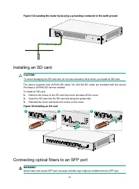
12 Figure 9 Grounding the router by burying a grounding conductor in the earth ground Installing an SD card CAUTION: To avoid damaging the SD card slot, do not use excessive force when you install an SD card. The device supports only JH318A SD cards. No JH318A SD cards are provided with the device. ...
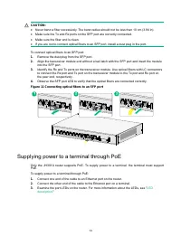
Page 17 - Supplying power to a terminal through PoE
13 CAUTION: • Never bend a fiber excessively. The bend radius should not be less than 10 cm (3.94 in). • Make sure the Tx and Rx ports on the SFP port are correctly connected. • Make sure the fiber end is clean. • If you are not to connect optical fibers to an SFP port, install a dust plug in the po...
Page 18 - Connecting Ethernet interface cables
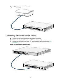
14 Figure 12 Supplying power to a terminal Connecting Ethernet interface cables 1. Connect one end of the cable to an Ethernet port on the router. 2. Connect the other end of the cable to the Ethernet port on a host. 3. Examine the port LEDs on the router. For more information about the LEDs, see &#...
Page 20 - Connecting the power cord; Verifying the installation; Accessing the router for the first time; Powering on the router
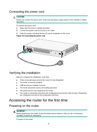
16 Connecting the power cord CAUTION: Before you connect the power cord, make sure the power supply system in the building is reliably grounded. To connect the power cord: 1. Make sure the router is reliably grounded. 2. Connect the power cord to the source AC outlet. 3. Insert the power cord plug i...
Page 21 - Observing the startup process
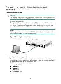
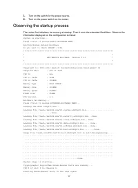
17 1. Turn on the switch for the power source. 2. Turn on the power switch on the router. Observing the startup process The router first initializes its memory at startup. Then it runs the extended BootWare. Observe the information displayed on the configuration terminal: System is starting... Press...
Page 22 - Configuring basic settings for the router
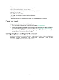
18 …… Cryptographic Algorithms Known-Answer Tests passed. Startup configuration file does not exist. Performing automatic configuration... Press CTRL_D to break. Line con0 is available. Press ENTER to get started. Press Enter and the system displays the following prompt: <Sysname> This prompt ...
Page 23 - Troubleshooting; Power supply failure; No display on the configuration terminal; Symptom
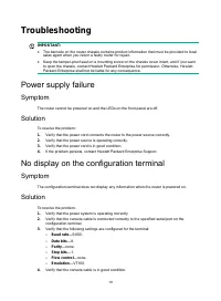
19 Troubleshooting IMPORTANT: • The barcode on the router chassis contains product information that must be provided to local sales agent when you return a faulty router for repair. • Keep the tamper-proof seal on a mounting screw on the chassis cover intact, and if you want to open the chassis, con...
Page 24 - Garbled display on the configuration terminal; No response from the serial port; Solution; Restoring the factory settings; Scenario 1
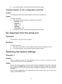
20 5. If the problem persists, contact Hewlett Packard Enterprise Support. Garbled display on the configuration terminal Symptom The configuration terminal has garbled display when the router is powered on. Solution To resolve the problem: 1. Verify that the following settings are configured for the...
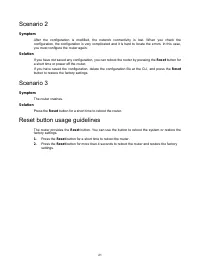
Page 25 - Scenario 2; Scenario 3; Reset button usage guidelines
21 Scenario 2 Symptom After the configuration is modified, the network connectivity is lost. When you check the configuration, the configuration is very complicated and it is hard to locate the errors. In this case, you must configure the router again. Solution If you have not saved any configuratio...
Page 26 - Chassis views
22 Appendix A Chassis views and technical specifications Chassis views The figures in this appendix are for illustration only. JH300A Figure 16 Front view (1) Gigabit Ethernet LAN ports (GE2 to GE9) (2) Gigabit Ethernet WAN port (GE0) (3) Gigabit combo interface (GE1/SFP1) (4) Console port (CON/AUX)...
Page 27 - Technical specifications
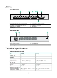
23 JH301A Figure 18 Front view (1) Gigabit Ethernet LAN ports (GE2 to GE9) (2) Gigabit Ethernet WAN port (GE0) (3) Gigabit combo interface (GE1/SFP1) (4) Console port (CON/AUX) (5) Reset button (RESET) (6) SD card slot (7) USB port Figure 19 Rear view (1) AC power receptacle (2) Grounding screw (3) ...
Page 29 - Appendix B LEDs; LEDs
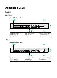
25 Appendix B LEDs LEDs JH300A Figure 20 Front panel LEDs (1) GE port yellow LED (2) GE port green LED (3) System status LED (SYS) (4) VPN status LED (5) SD card LED (6) Combo interface LED (7) GE0 port LED JH301A Figure 21 Front panel LEDs (1) GE port yellow LED (2) GE port green LED (3) System sta...
Page 31 - Index
27 Index A AC troubleshooting power supply failure, 19 accessories (installation), 4 Appendix A chassis views and technical specifications, 22 B LEDs, 25 C cable installing interface cable, 14 troubleshooting no response from serial port, 20 chassis cooling and ventilation, 3 chassis views, 22 JH300...