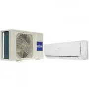
Page 2 - Contents
Contents Domestic air conditioner Contents 1. Introduction ............................................................................................12. Specifications.........................................................................................73. Sensors list ............................
Page 3 - Introduction; Model name explanation; The maximum combination number
Introduction Domestic air conditioner 1 Introduction 1.1 Model name explanation 1 1 U 7 S A B F A R The maximum combination number Type of outdoor unit : U (normal type) Nominal cooling capacity (7100W) Platform of outdoor units: S (S platform) Australia Version number Heat pump & R32 refrigeran...
Page 4 - Warning
Introduction Domestic air conditioner 1.2 Safety Cautions Be sure to read the following safety cautions before conducting repair work. The caution items are classified into “Warning” and “Caution”. The “Warning” items are especially important since they can lead to death or serious injury if they ar...
Page 10 - Note: the data are based on the conditions shown in the table below; Sensors list
Specification Domestic air conditioner Note: the data are based on the conditions shown in the table below h t g n e l g n i p i P g n it a e h g n il o o cIndoor: 27 DB/19 WBOutdoor: 35 DB/24 WB Indoor:20 DBOutdoor: 7 DB/6 WB 5m 3 Sensors list type Description Qty 3 in 1 it c e t e d r o f d e s u ...
Page 12 - Operation range
Operation range Domestic air conditioner 5 Operation range -10 0 -20 16 32 -10 -20 -15 10
Page 16 - Wiring diagrams; OUTDOOR UNIT WIRING DIAGRAM; OUTDOOR PCB
Functions and control Domestic air conditioner Wiring diagrams 14 THE CAPACITOR RETAINS HIGH VOLTAGE EVEN AFTER THE PLUG-OFF. FOR YOUR ● SAFETY, BE SURE TO WAIT AT LEAST 5 MINUTES.AFTER PLUG OFF AND USE A TESTER TO CONFIRM THE VOLTAGE BETWEEN CONNECTOR CN25 AND CN28(ON MAIN PCB BOARD) IS LESS THAN D...
Page 17 - Functions and Control; Main functions and control specification; The operation frequency of outdoor unit and its control
Functions and control Domestic air conditioner 7. Functions and Control 7.1 Main functions and control specification 7.1.1 The operation frequency of outdoor unit and its control 7.1.1.1 The operation frequency control of compressor 7.1.1.2 The starting of compressor 7.1.1.3 The speeds of increasing...
Page 18 - The outdoor fan control when refrigerating or dehumidifying
Functions and control Domestic air conditioner 16 Z H 4 7 2 z h _ x a M 2 3 < c _ h W 2 3 Wh_c ≥ 40 Max_hz3 90 HZ Remarks: the above are not only the maximum frequency limitations of the complete appliance which are affected by the environment, but also the maximum ability limitation of the syste...
Page 19 - Functions and control; The control of the outdoor electronic expansion valve; Four way control; Domestic air conditioner
Functions and control 7.1.3 ˖ The control of the outdoor electronic expansion valve When starting the compressor: the opening size of the valve must be guaranteed to have entered into the standard opening size, and then the compressor can be started. When refrigeration is in vain (the machine is shu...
Page 20 - Protection function; TTC high temperature-preventing protection
Functions and control 7.1.5 ˖ Protection function 7.1.5.1 ˖ TTC high temperature-preventing protection Once the machine is started, it can run TTC overheating protection of air-blowing, but air-blowing sensor malfunction must alarm after 4 minutes during which the compressor is started (during the c...
Page 23 - Value of Thermistor
Functions and control 7.2 Value of Thermistor Domestic air conditioner 7.2.1 Outdoor Unit Ambient Sensor, Defrosting Sensor, Pipe sensor R25 ć =10K ¡f 3% B25 ć /50 ć =3700K f 3% Temp.( ć ) Max.(KΩ) Normal(KΩ) Min.(KΩ) Tolerance( ć ) -30 165.2170 147.9497 132.3678 -1.94 1.75 -29 155.5754 139.5600 125...
Page 32 - Dimensional drawings
Dimensinal drawings Domestic air conditioner 8.Dimensional drawings 9.Center of gravity 920 1018 762 385 385 920 12.7 3/4 920 288 762 374 385 132 30
Page 33 - Parameter of primary electronic appliance
Connector Wiring Diagram Domestic Air Conditioner 1 .Service Diagnosis 1 .1.1 Caution for Diagnosis The operation lamp flashes when any of the following errors is detected.1.When a protection device of the indoor or outdoor unit is activated or when the thermistor malfunctions,disabling equipment op...
Page 34 - .3.1 Thermistor or Related Abnormality; .3 Error Codes and Description indoor display
Connector Wiring Diagram Domestic Air Conditioner 3 2 1 .3.1 Thermistor or Related Abnormality 1 .3 Error Codes and Description indoor display Code indication fault description Indoor displaying panel code indication Outdoor (LED1 flash times) Other display Only For 498 and 498A display (Red/Green T...
Page 35 - Indoor AC fan motor malfunction
Seivice diagnosis Domestic air conditioner 33 10 .3.2 EEPROM abnormal Indoor Display E4: indoor EEPROM error Outdoor display F12: Outdoor EEPROM error; Outdoor LED1 flash 1 times 10 10 10 10 10 10 10 10 .3.3 10 10 10 10 10 10 10 Indoor AC fan motor malfunction Indoor display E14This is caused by ind...
Page 39 - between IPM and outdoor PCB
1 0 .3.7 The communication fault between IPM and outdoor PCB Outdoor display: Seivice diagnosis Domestic air conditioner 37 F3 LED1 flash 4 times
Page 40 - or under voltage fault
1 0 .3.8 Power Supply Over or under voltage fault Outdoor display: Domestic air conditioner 38 Seivice diagnosis F19 LED1 flash 6 times
Page 41 - For Discharge Temperature
1 0 .3.9 Overheat Protection For Discharge Temperature Outdoor display: Seivice diagnosis Domestic air conditioner 39 F4 LED1 flash 8 times
Page 42 - fault between indoor and outdoor
1 0 .3.10 The communication fault between indoor and outdoor Indoor display E7 Outdoor display LED1 flash 15 times Domestic air conditioner 40 Seivice diagnosis
Page 46 - Compressor loss of synchronism detection
Seivice diagnosis Domestic air conditioner 44 1 0 .3.11 Outdoor Display F11 LED1 flash 18 times 1 0 .3.12 Outdoor Display F28 LED1 flash 19 times Compressor loss of synchronism detection Compressor position detection circuit fault
Page 47 - Performence and curves diagrams; Cooling capacity-temperature curves; cooling capacity and indoor/outdoor temp.curves
Performance and curves diagrams Domestic air conditioner 11.Performence and curves diagrams 11.1 Cooling capacity-temperature curves 45 indoor temp. DB/WB 10 ℃ 15 ℃ 20 ℃ 25 ℃ 30 ℃ 35 ℃ 38 ℃ 40 ℃ 43 ℃ 21/15 ℃ 6272 6124.8 5950 5600 5460 5152 4900 4606 4360 24/16 ℃ 6720 6510 6104 6020 5776.4 5390 5180 ...
Page 48 - Cooling power consumption value- temperature curves; po
Performance and curves diagrams Domestic air conditioner 11.2 Cooling power consumption value- temperature curves 46 indoor temp. DB/WB 10 ℃ 15 ℃ 20 ℃ 25 ℃ 30 ℃ 35 ℃ 38 ℃ 40 ℃ 43 ℃ 21/15 ℃ 1557 1644 1708 1802 1878 1992 2086 2158 2198 24/16 ℃ 1617 1689 1753 1840 1935 2048 2135 2200 2240 27/19 ℃ 1681 ...
Page 49 - Cooling discharge pressure curves; isch
Performance and curves diagrams Domestic air conditioner 11.3 Cooling discharge pressure curves 4 7 outdoor temp. (humidity 46%) DB/W B 21/15 27/19 35/24 10 1899 2010 2107 15 1949 2037 2141 20 1976 2064 2178 25 2079 2144 2287 30 2211 2385 2478 35 2429 2546 2674 38 2615 2734 2901 40 2940 3082 3234 43...
Page 50 - Cooling suction pressure curves; sucti
Performance and curves diagrams Domestic air conditioner 11.4 Cooling suction pressure curves 48 outdoor temp. (humidity 46%) DB/WB 21/15 27/19 35/24 10 9 2 0 1 6 8 8 7 5 7 15 0 4 0 1 5 9 8 5 6 7 20 0 5 0 1 3 1 9 2 7 7 25 2 7 0 1 2 2 9 3 1 8 30 2 8 0 1 1 7 9 6 5 8 35 9 3 1 1 1 8 9 4 6 8 38 910 1011 ...
Page 51 - Heating capacity-temperature curves; co
Performance and curves diagrams Domestic air conditioner 11.5 Heating capacity-temperature curves 49 outdoor temp. DB/WB 10 ℃ 20 ℃ 27 ℃ -15 ℃ 5194 4686 4190 -10 ℃ 6526 5877 5158 -7/-8 ℃ 7920 7181 6289 2/1 ℃ 9780 8722 7663 7/6 ℃ 9629 8477 7481 12/11 ℃ 9417 8268 6892 18/16 ℃ 7209 6537 5727 24/20 ℃ 594...
Page 52 - Heating power consumption value- temperature curves
Performance and curves diagrams Domestic air conditioner 11.6 Heating power consumption value- temperature curves 50 outdoor temp. DB/WB 10 ℃ 20 ℃ 27 ℃ -15 ℃ 1972 2141 2277 -10 ℃ 2216 2366 2515 -7/-8 ℃ 2424 2669 2800 2/1 ℃ 2578 2804 2988 7/6 ℃ 2303 2535 2660 12/11 ℃ 1894 2021 2149 18/16 ℃ 1515 1617 ...
Page 53 - Heating discharge pressure curves; dis
Performance and curves diagrams Domestic air conditioner 11.7 Heating discharge pressure curves 5 1 outdoor temp DB/WB 10 20 27 -15 7 6 8 2 4 6 7 2 4 4 6 2 -10 3 7 0 3 0 8 9 2 9 8 7 2 -7/-8 3 6 5 3 1 1 4 3 9 5 2 3 2/1 3 8 8 3 8 9 6 3 1 6 4 3 7/6 2 7 6 3 0 9 5 3 9 0 4 3 12/11 6 0 6 3 2 8 4 3 6 4 3 3 ...
Page 54 - Heating suction pressure curves; heating suction pressure and temp. curves
Performance and curves diagrams Domestic air conditioner 11.8 Heating suction pressure curves 52 outdoor temp DB/WB 10 20 27 -15 5 0 4 5 8 3 5 4 3 -10 7 4 4 8 2 4 8 9 3 -7/-8 1 5 5 2 3 5 2 9 4 2/1 0 7 6 1 5 6 1 1 6 7/6 3 0 8 4 8 7 4 4 7 12/11 4 0 9 4 8 8 4 4 8 18/16 1011 1051 1071 24/20 1197 1237 12...
Page 55 - 2 Circuit diagrams; Outdoor unit control board Circuit Diagrams
Circuit diagrams Domestic air conditioner 12 Circuit diagrams 12.1 Outdoor unit control board Circuit Diagrams 53
Page 57 - Module board Circuit Diagram
Circuit diagrams Domestic air conditioner 12.2 Module board Circuit Diagram 55 1 1 2 2 3 3 4 4 D D C C B B A A C00 9 103 IG 8 40A@100 ℃ 1 2 3 4 B G 1 D25XB60 C40 4 CBB21-474/630V C40 5 CBB21-474/630V R S1 0. 01/ 5W R21 5 10K R S2 0. 01 R00 3 100 R002 10K R007 10K R00 6 100 4 5 6 U V W C007 104 C01 3...
Page 58 - Sincere Forever; Haier Group; Zhen Lingyun
Circuit diagrams Domestic air conditioner Sincere Forever Haier Group Haier Industrial Park, No.1, Haier Road 266101, Qingdao, China_ Http //www.haier.com Edited by : Signed by : Approved by: Zhen Lingyun He Shiquan Zhang JingZhang Xianqiang
Page 59 - Wall Mounted Type
Wall Mounted Type ON/OFF-Series SERIES:70 PLATFORM This service information is designed for experienced repair te...
Page 60 - Removal of Outdoor panel
Removal of procedure 1 Domestic air conditioner 1.Removal of Outdoor panel Procedure Warning Be sure to wait 10 minutes or more after turnin...
Page 62 - Removal of Electrical Box
Removal of procedure 3 Domestic air conditioner 2.Removal of Electrical Box Procedure Warning Be sure to wait 10 minutes or more after turni...
Page 63 - Removal of Fan and Fan Motor
Removal of procedure 4 Domestic air conditioner 3.Removal of Fan and Fan Motor Procedure Warning Be sure to wait 10 minutes or more after tu...
Page 65 - Removal of fan motor bracket and partition
Removal of procedure 6 Domestic air conditioner 4.Removal of fan motor bracket and partition Procedure Warning Be sure to wait 10 minutes or...
Page 67 - Removal of compressor and heat exchanger
Removal of procedure 8 Domestic air conditioner 5.Removal of compressor and heat exchanger Procedure Warning Be sure to wait 10 minutes or m...
Page 70 - Drawing for the installation of indoor and outdoor units; Preparation; Installation Manual of Room Air Conditioner
F A C E D Drawing for the installation of indoor and outdoor units Necessary parts for piping Non-adhesive tapeAdhesive tapeSaddle (L.S) with screwsConnecting electric cable for indoor and outdoor Drain hose Heating insulating material Piping hole cover The marks from to in the gure are the parts nu...
Page 71 - Indoor unit
Indoor unit Fix to side bar and lintel a mounting bar, Which is separately sold, and then fasten the plate to the xed mounting bar. Refer to the previous article, “ When the mounting plate is position of wall hole. Make a hole of 60 mm in diameter, slightly descending to outside the wall.Install pip...