Page 3 - Table of Contents
1 2 3 6 8 8 8 9 11 12 12 13 13 14 14 15 15 16 17 19 20 21 How To Contact Us Controls & Components Machine Data Sheet Table Safety Instructions for Machinery Safety Guidelines – Definitions Important Safety Instructions Before Using the Air Compressor Power Supply When Installing or Moving the Co...
Page 4 - Compressor Controls; How To Contact Us
2 Compressor Controls Power Switch: This switch turns the compressor power ON and OFF . Pressure Relief Valve: If the pressure switch does not shut down the motor when pressure reaches the pre-set level, this valve will pop open automatically to prevent over-pressurization. To operate manually, pull...
Page 5 - Product Dimensions; Machine Data Sheet Table
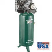
STATIONARY AIR COMPRESSORS Model # G0954 G0955 G0956 G0957 Product Dimensions Weight 305 lbs. 325 lbs. 380 lbs. Width (side-to-side)/Depth (front-to-back)/Height 30" x 22" x 66-1/2" 30" x 22" x 68" 31-1/2" x 26" x 67" 26" x 32" x 68" Footprint (Length/...
Page 8 - Safety Instructions for Machinery
6 OWNER’S MANUAL. Read and understand this owner’s manual BEFORE using machine. TRAINED OPERATORS ONLY. Untrained operators have a higher risk of being hurt or killed. Only allow trained/supervised people to use this machine. When machine is not being used, disconnect power, remove switch keys, or l...
Page 10 - Things You Should Know; Safety Guidelines - Definitions; WARNING; Before Using the Air Compressor
8 Safety is a combination of common sense, staying alert, and knowing how your compressor works. Read this manual to understand this compressor. DANGER means if safety information is not followed someone will be seriously injured or killed. WARNING means if safety information is not followed someone...
Page 11 - Availability; Full-Load Current Rating; Circuit Requirements for 220V; Power Supply
9 WARNING CAUTION Availability Before installing the machine, consider the availability and proximity of the required power supply circuit. If an existing circuit does not meet the requirements for this machine, a new circuit must be installed. To minimize the risk of electrocution, fire, or equipme...
Page 12 - Connection Type; Grounding Requirements; Extension Cords
10 WARNING Connection Type A permanently connected (hardwired) power supply is typically installed with wires running through mounted and secured conduit. A disconnecting means, such as a locking switch (see following figure) must be provided to allow the machine to be disconnected (isolated) from t...
Page 13 - To Reduce the Risk of a Dangerous; When Installing or Moving the Compressor
11 NOTICE This compressor is extremely top heavy. It must be bolted to the floor with vibration pads (see figure below) before operating to prevent equipment damage, injury, or death. DO NOT tighten bolts completely as this may cause stress to the tank welds. To Reduce the Risk of a Dangerous Enviro...
Page 14 - Inspect Your Work Area; Hardwiring to Power Supply; Before Each Use
12 WARNING Inspect Your Work Area 1. Keep work area clean. Cluttered areas and benches invite accidents. 2. The floor must not be slippery from wax or dust. Inspect Your Compressor 1. To reduce the risk of injury from accidental starting, turn the switch off and disconnect power. 2. If any part is m...
Page 15 - Ears
13 Dress for Safety 1. Wear safety glasses meeting ANSI Z87.1 (or in Canada CSA Z94.3-99) and use hearing protection when operating the unit. Everyday glasses are not safety glasses. 2. Wear shoes to prevent shock hazards. 3. Tie back long hair. Pay Attention to Your Hands Keep fingers away from run...
Page 16 - Spraying Precautions
14 Never point a nozzle or spray gun at yourself or any other person or animal. Accidental discharge may result in serious injury. Reduce the Risk of a Dangerous Environment Extreme caution should be taken when spraying flammable liquids as the spark from a motor or pressure switch may cause a fire ...
Page 17 - CAUTION; Glossary of Terms
15 CAUTION Air Filter Porous element contained within a metal or plastic housing attached to the compressor cylinder head which removes impurities from the intake air of the compressor. Air Tank Cylindrical component which contains the compressed air. Check Valve Device which prevents compressed air...
Page 18 - Draining the Tank
16 Draining the Tank Oil and moisture residue must be drained from the air receiver daily or after each use. Accumulations of oil residue in the receiver can be ignited by embers of carbon created by the heat of compression—causing an explosion, damage to property, and injury to personnel. Do not op...
Page 19 - TROUBLESHOOTING GUIDE
17 TROUBLESHOOTING GUIDE Low discharge pressure. 1. Compressor too small for application. 2. Air leaks. 3. Restricted intake air.4. Blown gasket(s).5. Broken or misaligned valves. 1. Reduce air demand or use a compressor with more air capacity. 2. Listen for air leaks. Apply a soap solution to all f...
Page 21 - To order parts, or other services and inquiries, contact us by; Maintenance Operations
19 WARNING To order parts, or other services and inquiries, contact us by phone at (832) 415-6995 or email at [email protected]. 1. Do regular maintenance; keep all nuts, bolts, and screws tight to be sure equipment is in safe working condition. 2. Inspect tank yearly for rust, pin holes, or any oth...
Page 22 - Wiring
20 WARNING WARNING WARNING (G0957 Shown) ALL ELECTRICAL WIRING SHOULD BE DONE BY A QUALIFIED ELECTRICIAN! Adequate wiring and motor protection should be provided for all stationary compressors. Wiring used for other machinery should not be used. A qualified electrician familiar with local electrical...
Page 23 - Parts
1 2 3 25 4 26 27 30 31 32 35 36 37 38 39 40 41 42 43 44 45 29 28 27 23 5 6 7 8 9 10 11 12 13 14 15 16 19 20 21 22 12 11 16 33 34 22 G0954 Pump Parts 21
Page 26 - G0954 Tank & Motor Parts List
REF DESCRIPTION QTY REF DESCRIPTION QTY 101 TANK 1 116 PUMP DISCHARGE LINE 12MM 1 103 MOTOR 3HP 240V 1-PH 1 117 DISCHARGE PIPE 6MM 1 104 KEY 3/16 X 3/16 X 1-3/8 1 118 PRESSURE GAUGE 1/8" NPT 1 105 MOTOR PULLEY 1 119 FLANGE JOINT 1/2" NPT X 2" 1 106 V-BELT A47 1 120 FLANGE JOINT 1/4" ...
Page 30 - G0955 Tank & Motor Parts List
G0955 Tank & Motor Parts List REF DESCRIPTION QTY REF DESCRIPTION QTY 101 TANK 1 116 PUMP DISCHARGE LINE 12MM 1 103 MOTOR 5HP 230V 1-PH 1 117 DISCHARGE PIPE 6MM 1 104 KEY 3/16 X 3/16 X 1-3/8 1 118 PRESSURE GAUGE 1/8" NPT 1 105 MOTOR PULLEY 1 119 FLANGE JOINT 1/2" NPT X 2" 1 106 V-BEL...
Page 32 - G0956 Tank & Motor Parts List
REF DESCRIPTION QTY REF DESCRIPTION QTY 101 TANK 1 116 PUMP DISCHARGE LINE 12MM 1 103 MOTOR 5HP 230V 1-PH 1 117 DISCHARGE PIPE 6MM 1 104 KEY 3/16 X 3/16 X 1-3/8 1 118 PRESSURE GAUGE 1/8" NPT 1 105 MOTOR PULLEY 1 119 FLANGE JOINT 1/2" NPT X 2" 1 106 V-BELT A51 1 120 FLANGE JOINT 1/4" ...
Page 36 - G0957 Tank & Motor Parts List
REF DESCRIPTION QTY REF DESCRIPTION QTY 101 TANK 1 119 MOTOR PULLEY 1 103 FLANGE JOINT 1/4" 1 120 MOTOR CORD 12G 3W 16" 1 104 BALL DRAIN VALVE 1/4" 1 121 V-BELT B53 5L560 1 105 BALL VALVE 1/2" 1 122 HEX BOLT M8-1.25 X 25 4 106 FLANGE JOINT 1/2" 1 123 FLAT WASHER 8MM 8 107 THREADE...