Page 2 - Table of Contents
Table of Contents Safety Precautions . . . . . . . . . . . . . . . . . . . . . . . . . . . . . . . . . . . . . . . . . . . . . . . . 2 Nomenclature . . . . . . . . . . . . . . . . . . . . . . . . . . . . . . . . . . . . . . . . . . . . . . . . . . . 3 System Requirements . . . . . . . . . . . . . . ...
Page 3 - SAFETY PRECAUTIONS; Please read the following before installation.; NOTICE; WARNING
SAFETY PRECAUTIONS Please read the following before installation. This is the safety alert symbol. It is used to alert you to potential personal injury hazards. Obey all safety messages that follow this symbol to avoid possible injury or death. This mark indicates procedures which, if improperly per...
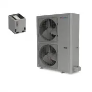
Page 4 - Outdoor Unit; NOMENCLATURE
Page 5 - SYSTEM REQUIREMENTS
SYSTEM REQUIREMENTS REFRIGERANT CHARGE ELECTRICAL REQUIREMENTS Notes: 1) System must be on a single dedicated circuit.2) Main power is supplied to the outdoor unit.3) Use table above to size over current protection.4) Follow all local building codes and NEC (National Electrical Code) regulations. In...
Page 6 - SUGGESTED TOOLS
• Standard Wrench • Adjustable/Crescent Wrench • Torque Wrench • Hex Keys or Allen Wrenches • Drill & Drill Bits • Hole Saw • Pipe Cutter • Screw drivers (Phillips & Flat blade) • Manifold and Gauges • Level • R410A Flaring Tool • Clamp on Amp Meter • Vacuum Pump • Safety Glasses • Work Glov...
Page 7 - INSTALLATION SITE INSTRUCTIONS; Indoor Unit; Select a site that allows for the following:; Ceiling
INSTALLATION SITE INSTRUCTIONS Indoor Unit Select a site that allows for the following: 1. Ensure the installation complies with the installation minimum dimensions (defined below) and meets the minimum and maximum connecting piping length and maximum change in elevation as defined in the System Req...
Page 8 - heating mode to a safe location.; Select a site that allows the following:; Minimum Outdoor Clearances
Air inlet Air outlet 20 in (0.5 m) 20 in (0.5 m) 39 in (1.0m) 20 in (0.5 m) 78 in (2.0 m) 1. Install the outdoor unit at a location that is capable of withstanding twice the weight of the unit. 2. Install the outdoor unit where it is convenient to connect refrigerant lines to the indoor units. 3. In...
Page 9 - CROWN INDOOR UNIT INSTALLATION; Crown Unit Mounting Bracket Diagram (inches); Crown
PIPE SIZE – in (mm) Unit Size (BtuH) Liquid Line Suction /Gas Line 9,000 1/4 (6) 1/2 (12) 12,000 1/4 (6) 1/2 (12) 18,000 1/4 (6) 5/8 (16) CROWN INDOOR UNIT INSTALLATION Model A B C CROWN09HP230V1B 37.8 (960) 12.6 (320) 8.0 (205) CROWN12HP230V1B 37.8 (960) 12.6 (320) 8.0 (205) CROWN18HP230V1B 37.8 (9...
Page 10 - TERRA INDOOR UNIT INSTALLATION; Terra
TERRA INDOOR UNIT INSTALLATION Model A B C TERRA09HP230V1AH 34.1 (866) 11.5 (292) 8.2 (208) TERRA12HP230V1AH 34.1 (866) 11.5 (292) 8.2 (208) TERRA18HP230V1BH 40.1 (1018) 12.6 (319) 9.1 (231) TERRA24HP230V1BH 46.4 (1178) 12.8 (325) 10.4 (264) PIPE SIZE – in (mm) Unit Size (BtuH) Liquid Line Suction /...
Page 11 - Terra Unit Mounting Bracket Diagrams
TERRA INDOOR UNIT INSTALLATION Terra Unit Mounting Bracket Diagrams (inches) 9K and 12K Unit 18K Unit 24K Unit Left Right (Rear piping hole) (Rear piping hole) Left Right (Rear piping hole) Left (Rear piping hole) (Rear piping hole) Right (Rear piping hole) 10
Page 12 - VIREO INDOOR UNIT INSTALLATION; Vireo
VIREO INDOOR UNIT INSTALLATION B C A 11 Model A B C VIR09HP230V1B 33.4 (848) 11.4 (290) 8.2 (208) VIR12HP230V1B 33.4 (848) 11.4 (290) 8.2 (208) VIR18HP230V1B 38.2 (970) 11.8 (300) 8.8 (224) VIR24HP230V1B 42.4 (1077) 12.8 (325) 9.7 (246) PIPE SIZE – in (mm) Unit Size (BtuH) Liquid Line Suction /Gas L...
Page 13 - Vireo Unit Mounting Bracket Diagrams
Vireo Unit Mounting Bracket Diagrams (inches) VIREO INDOOR UNIT INSTALLATION 9K and 12K Unit 18K Unit 24K Unit 4.6 21.4 7.3 4 27 7.3 8.1 27 6.0 3.1 7.4 1.4 1.4 1.57.5 5.5 1.5 1.6 1.6 2.3 2.3 2.3 2.3 2.8 2.8 12 Left Right (Rear piping hole) (Rear piping hole) Right (Rear piping hole) Right (Rear pipi...
Page 14 - Piping Design and Layout; INDOOR UNIT INSTALLATION
Piping Design and Layout The piping design and layout are critical factors for the overall performance and reliability of the system. Find the desired locations for each indoor unit and the outdoor unit. Then measure and record the piping lengths and heights as directed below to qualify the piping d...
Page 15 - Piping Length Requirements
Piping Length Requirements The system piping layout must take in the constraints of horizontal length on system performance. The outdoor unit has a length limit in which it can properly circulate refrigerant in the system. Capacity Size (BtuH) Distance ft (m) 18,000 33 (10) 24,000 65 (20) 30,000 82 ...
Page 16 - Piping Height Requirements; Oil Return Bend
Piping Height Requirements The system piping layout must take in the constraints of vertical height on system performance. The outdoor unit has a vertical height limit in which it can properly circulate refrigerant in the system. INDOOR UNIT INSTALLATION Capacity Size (BtuH) Distance ft (m) 18,000 3...
Page 17 - OUTDOOR UNIT INSTALLATION; Outdoor Unit Dimensions
OUTDOOR UNIT INSTALLATION 18K Unit 24K Unit Outdoor Unit Dimensions 16 35.1 38.0 22.0 35.1 22.0 13.4 17.3 38.6 13.4 15.6 27.6 31.1 14.5 14.5
Page 19 - Drain Fitting Installation
Install Ground Pad or Wall Hangers 1. Determine proper location for outdoor unit.2. Follow all instructions provided by manufacturer for installing wall hangers or ground pad.3. Verify the wall hangers or ground pad can safely support the weight of the outdoor unit.4. Verify the wall hangers or grou...
Page 20 - Install Mounting Bracket; Attach the mounting bracket to the indoor unit.; High Wall Indoor Installation
INDOOR UNIT INSTALLATION Install Mounting Bracket 1. Attach the mounting bracket to the indoor unit. 2. Find the horizontal center of the indoor unit. 3. Mark the center of the indoor unit on mounting bracket for future reference. NOTE: The center of the mounting bracket is not the center of the ind...
Page 21 - Refrigerant Piping; Expandable foam insulation may be added to fill large; Drill Hole in Wall; Table of Wall Hole Size per Unit Size; Wall Hole Diagram
Carefully cut hole in the side of the front panel for piping to enter indoor unit as shown below. Find and mark the proper location for the wall hole. Use table below to determine recommended wall hole size for your unit size. 3. Cut the wall hole with a 5° to 10° downward slant to the outdoors. 4. ...
Page 22 - PIPING INSTALLATION; CAUTION; Piping Preparation; connections are made.
Refrigerant Piping PIPING INSTALLATION Use refrigeration grade piping ONLY. Uses of other piping will void the Manufacturer’s Warranty. CAUTION 21 Piping Preparation • Do not open service valves or remove protective caps from tubing ends until all connections are made. • Keep tubing free of dirt, sa...
Page 23 - Over tightening may damage flare connections and cause leaks.; Refrigerant Piping Connections to Indoor Unit; through wall hole from outdoor to the indoor unit.; Torque Table
PIPING INSTALLATION 4. Properly align piping and tighten flare nut using a standard wrench and a torque wrench as shown in figure to the below. Carefully tighten flare nuts to correct torque level referring to the Torque Table above. NOTE: Over tightening may damage flare connections and cause leaks...
Page 24 - How to Relocate Drain Hose from Left to Right Side (if required); Indoor Drain Piping
How to Relocate Drain Hose from Left to Right Side (if required) 1. Locate drain plug on right side of the drain tray. Firmly grab it and remove from drain tray. 2. Locate drain tube on the left side of drain tray. Remove hose clamp and twist drain tube counter-clockwise and gently pull to remove fr...
Page 25 - Correct Incorrect Incorrect
Indoor Drain Piping The indoor wall unit uses a gravity drain system. There is no internal condensate pump. The drainhose must slope downward with no kinks, raises or fluctuations. PIPING INSTALLATION Drain hose Outlet pipe 1. Connect the field supplied drain hose to the outlet pipe of indoor wall u...
Page 26 - Piping Connections to Outdoor Unit; Carefully bend and adjust length of refrigerant
Piping Connections to Outdoor Unit 1. Remove service valve cover (if provided) to access the service valves and refrigerant ports. The outdoorunit refrigerant port sizes vary with unit size. See System Requirement Section for refrigerant port sizes. 2. Carefully bend and adjust length of refrigerant...
Page 27 - wrench as shown in the indoor piping section.
PIPING INSTALLATION 3. Apply a small amount of refrigerant oil to the flare connection on the refrigerant pipe. 4. Properly align piping and tighten flare nut using a standard wrench and a torque wrench as shown in the indoor piping section. 5. Carefully tighten flare nuts to correct torque level re...
Page 28 - POWER AND WIRING INSTALLATION
POWER AND WIRING INSTALLATION To the power supply To unit B Power cord To unit A connecting cable L1 L2 P connecting cable c cable T L1 L2 cable L1 L2 L cable c cable T cable L Power cord L1 L2 L L1 L2 To the power supply To unit A L1 L2 c cable connecting cable To unit B connecting cable To unit C ...
Page 30 - High Wall Indoor Wire Connection; terminal block on indoor unit.; Typical Terminal
POWER AND WIRING INSTALLATION High Wall Indoor Wire Connection Disconnect all electrical power to indoor and outdoor units including disconnects, fuses and circuit breakers. Lockout and tag all disconnect switches. 1. Open front cover of indoor unit and remove field wiring terminal block cover. 2. P...
Page 31 - Outdoor Unit Wire Connections; Multiple Port Conduit
Outdoor Unit Wire Connections Disconnect all electrical power to unit including disconnects, fuses and breakers. 1. Remove the service panel on right side of the outdoor unit. 2. Insert interconnecting wires and main power wires through the wire holes on conduit mounting bracket. 3. Secure main powe...
Page 33 - UNIT DAMAGE HAZARD –; Never use the system compressor as a vacuum pump.; Using Vacuum Pump; Fully open the low side of manifold gauge.; TESTING AND INSPECTION; Manifold Gauge
Leaking Test Leak test each indoor unit, one unit at a time. Repeat the leak test sequence for each indoor unit. 1. Connect the charging hose of the manifold valve to charge the end of the low-pressure valve.2. Add dry nitrogen to a pressure of 500 lbs. Tightly close both high- and low-pressure valv...
Page 34 - Evacuate using either deep vacuum or triple evacuation method.; Additional Charge
Using Vacuum Pump (con’t): 5. Evacuate using either deep vacuum or triple evacuation method. 6. After evacuation is complete, fully close the low side of manifold gauge and stop operation of vacuum pump. 7. Disconnect charge hose from charge connection of the low side service valve. 8. Fully open se...
Page 36 - TROUBLESHOOTING; PROBLEM
35 TROUBLESHOOTING PROBLEM System does not restart. Indoor unit emits unpleasant odorwhen started. You hear a“water flowing” sound. A thin fog or vapor coming out of the indoor unit when system isrunning. You hear a slight cracking soundwhen the system stops or starts. The system will not run. The u...
Page 38 - DIAGNOSTIC CODES; Troubleshooting
37 DIAGNOSTIC CODES X-fan Mode Indoor Evap Coil Temperature Sensor Malfunction Gas valve temperature sensoris open/short circuited System ConfigurationMalfunction Communication wire error orelectronic expansion valve malfunction Wrong connection of communicationwire or malfunction of electronic expa...
Page 42 - APPENDIX A; Authorized Indoor Unit Combinations
Outdoor Model Size 2-Zone 3-Zone 4-Zone 5-Zone APPENDIX A Authorized Indoor Unit Combinations 41 9+9 9+12 9+9 9+129+18 12+1212+18 18+18 9+9 9+129+18 9+24 12+1212+18 12+24 18+1818+24 9+9 9+129+18 9+24 12+1212+18 12+24 18+1818+2424+24 9+9 9+129+18 9+24 12+1212+18 12+24 18+1818+2424+24 9+9+9 9+9+129+9+...
Page 43 - LIMITED WARRANTY STATEMENT
LIMITED WARRANTY STATEMENT FOR WARRANTY SERVICE OR REPAIR: Contact your installing contractor. You may find the installer’s name on the equipment or in your Owner’s packet. Complete product registration below and send back by email to [email protected]. GREE distributor (hereinafter “Company”) warra...