Page 2 - TABLE OF CONTENTS; App
TABLE OF CONTENTS Introduction . . . . . . . . . . . . . . . . . . . . . . . . . . . . . . . . . . . . . . 3Key Features . . . . . . . . . . . . . . . . . . . . . . . . . . . . . . . . . . . . . . 3What’s in the Package . . . . . . . . . . . . . . . . . . . . . . . . . . . . . . 3Product Overview . ...
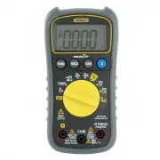
Page 4 - PRODUCT OVERVIEW
PRODUCT OVERVIEW Fig. 1 shows the labels and positions of the controls, LCD and physicalstructures of the meter. Fig. 2 shows all possible indications on the LCD.Familiarize yourself with the functions and meanings of all controls, indicationsand connectors before moving on to the safety, setup and ...
Page 5 - SAFETY INSTRUCTIONS; Warning
1. Indicates DC voltage or current measurement 2. Indicates AC voltage or current measurement 3. Negative polarity indicator 4. Bluetooth enabled indicator 5. Indicates Auto power off function is enabled 6. Low battery indicator 7. Indicates detection of non- contact voltage 8. Autoranging mode indi...
Page 7 - SETUP INSTRUCTIONS; INSTALL BATTERY; To open the compartment:; ) Secure the battery compartment by replacing the cover/stand and; Symbol
SETUP INSTRUCTIONS INSTALL BATTERY Turn the meter over to gain access to the battery compartment. To open the compartment: 1) Use a small Phillips-head screwdriver to remove the single screw in the middle of the one-piece battery compartment cover/flip-up stand. 2) Remove the cover/stand and set it ...
Page 8 - OPERATING INSTRUCTIONS; GENERAL INSTRUCTIONS
OPERATING INSTRUCTIONS GENERAL INSTRUCTIONS All parameters are measured through the included test leads. Unless you aremeasuring currents larger than 400 mA, plug the red test lead into thejack and the black test lead into the C OM jack. To measure currents larger than 400 mA, plug the red lead into...
Page 9 - MEASURING AC or DC CURRENT
DISABLING AUTO POWER OFF By default, the DMM will automatically power itself off following any period of15 minutes of front-panel inactivity. The icon at the upper left of the LCD indicates that the Auto Power Off function is enabled. To disable the APO function , press and hold the FUNC button whil...
Page 11 - MEASURING RESISTANCE; MEASURING TEMPERATURE
MEASURING RESISTANCE •• Warning •• To avoid electrical shock or damage to the meter when measuring resistance,turn off all power to the circuit and discharge all high-voltage capacitors. (1) Turn the rotary switch to the position and press the FUNC button until Ω , k Ω or M Ω appears on the right si...
Page 12 - CHECKING FOR CONTINUITY; CHECKING THE INTEGRITY OF A DIODE
CHECKING FOR CONTINUITY •• Warning •• To avoid possible damage to the meter or other equipment, turn off the powersource and discharge all high-voltage capacitors. (1) Turn the rotary switch to the position and press the FUNC button until the icon appears in the upper right corner of the LCD. (2) Pl...
Page 13 - CHECKING BATTERY VOLTAGE; USING THE NCV DETECTOR; To check whether a line, cable or AC outlet is “hot”; USING THE DMM WTH THE ToolSmart
CHECKING BATTERY VOLTAGE •• Warning •• To avoid possible electrical shock or damage to the meter, do not apply avoltage greater than 600V between the meter’s and COM jacks. (1) Turn the rotary switch to the 9V or 1.5V position, corresponding to the nominal voltage of the battery to be tested. (2) Pl...
Page 14 - SPECIFICATIONS; Attribute
SPECIFICATIONS Parameter orFeature/Function Attribute Specification AC voltage Measurement ranges 0 to 4V/40V/400V/600V Measurement accuracy ±(1% of reading + 10 digits) Maximum resolution 1mV DC voltage Measurement ranges 0 to 400mV/4V/40V/400V/600V Measurement accuracy ±(0.8% of reading + 5 digits...
Page 16 - OPERATING & MAINTENANCE TIPS; To replace a blown fuse:
OPERATING & MAINTENANCE TIPS When the icon appears in the upper left corner of the LCD, immediately replace the meter’s “9V” battery by following the instructions on page 7. To replace a blown fuse: 1. Power off the meter. 2. Unplug the test leads. 3. Turn the meter over and loosen the small Phi...
Page 18 - FCC STATEMENT; • Reorient or relocate the receiving antenna.; Caution; : Any changes or modifications not expressly approved by the party
FCC STATEMENT This device complies with part 15 of the FCC Rules. Operation is subject to thefollowing two conditions: (1) This device may not cause harmful interference,and (2) This device must accept any interference received, includinginterference that may cause undesired operation. This equipmen...
Page 19 - NOTES
NOTES __________________________________________________________ __________________________________________________________ __________________________________________________________ __________________________________________________________ __________________________________________________________...
Page 20 - GENERAL TOOLS & INSTRUMENTS
GENERAL TOOLS & INSTRUMENTS 75 Seaview Drive Secaucus, NJ 07094 PHONE (212) 431-6100 FAX (212) 431-6499 TOLL FREE (800) 697-8665 e-mail: [email protected] www.generaltools.com TS04 User’s Manual Specifications subject to change without notice ©2016 GENERAL TOOLS & INSTRUMENTS NOTICE - WE ARE...
Page 21 - MULTÍMETRO DIGITAL; MANUAL DEL USUARIO
MULTÍMETRO DIGITAL MANUAL DEL USUARIO TS04 Lea cuidadosamente todo este manual antes de usar este producto.
Page 22 - ÍNDICE; ToolSmart
ÍNDICE Introducción . . . . . . . . . . . . . . . . . . . . . . . . . . . . . . . . . . . . . 23Características principales . . . . . . . . . . . . . . . . . . . . . . . . . 23Contenido de la caja . . . . . . . . . . . . . . . . . . . . . . . . . . . . . . 23Descripción general del producto . . . . ...
Page 24 - DESCRIPCIÓN GENERAL DEL PRODUCTO
DESCRIPCIÓN GENERAL DEL PRODUCTO La Fig. 1 muestra los nombres y ubicación de la pantalla, controles y la estructurafísica del multímetro. La Fig. 2 muestra todas las indicaciones posibles de la pantallaLCD. Aprenda las funciones y el significado de todos los controles, indicadores yconectores antes...
Page 25 - INSTRUCCIONES DE SEGURIDAD; Advertencia
1. Indica la medición de voltaje o corriente de CC 2. Indica la medición de voltaje o corriente de CA 3. Indicador de polaridad negativa 4. Indicador de Bluetooth activado 5. Indica que la función de apagado automático estáactivada 6. Indicador de batería baja 7. Indica la detección de voltaje sin c...
Page 27 - INSTRUCCIONES DE PREPARACIÓN; INSTALACIÓN DE LA BATERÍA; Para abrir el compartimiento:; de la tapa del compartimiento de la batería/pie de apoyo plegable.; Símbolo Descripción
INSTRUCCIONES DE PREPARACIÓN INSTALACIÓN DE LA BATERÍA Voltee el medidor para obtener acceso al compartimiento de la batería. Para abrir el compartimiento: 1) Use un pequeño destornillador Phillips para remover el único tornillo del centro de la tapa del compartimiento de la batería/pie de apoyo ple...
Page 28 - INSTRUCCIONES DE OPERACIÓN; INSTRUCCIONES GENERALES
INSTRUCCIONES DE OPERACIÓN INSTRUCCIONES GENERALES Todos los parámetros se miden con las puntas de prueba incluidas. A menos queesté midiendo corrientes de más de 400 mA, conecte la punta de prueba roja en elenchufe y la punta de prueba negra en el enchufe COM . Para medir corrientes de más de 400 m...
Page 29 - MEDICIÓN DE CORRIENTE DE CA O CC
DESACTIVACIÓN DEL APAGADO AUTOMÁTICO Por defecto, el DMM se apagará automáticamente luego de 15 minutos deinactividad del panel frontal. El ícono en el extremo superior izquierdo de la pantalla indica que la función de apagado automático está activada. Para desactivar la función APO , mantenga presi...
Page 31 - MEDICIÓN DE RESISTENCIA; MEDICIÓN DE TEMPERATURA
MEDICIÓN DE RESISTENCIA •• Advertencia •• Para evitar descargas eléctricas o daños al medidor al medir resistencia,desconecte toda alimentación al circuito y descargue todos los condensadores dealto voltaje. (1) Gire el selector rotativo a la posición y presione el botón FUNC hasta aparezca Ω , k Ω ...
Page 32 - VERIFICACIÓN DE CONTINUIDAD; VERIFICACIÓN DE DIODOS
PUNTA DE PRUEBA ROJA PUNTA DE PRUEBA NEGRA VERIFICACIÓN DE CONTINUIDAD •• Advertencia •• Para evitar posibles daños al medidor o a otros equipos, desconecte la alimentaciónal circuito y descargue todos los condensadores de alto voltaje. (1) Gire el selector rotativo a la posición y presione el botón...
Page 33 - VERIFICACIÓN DE VOLTAJE DE BATERÍAS; USO DEL DETECTOR NCV; NCV; USANDO EL DMM CON LA APLICACIÓN ToolSmart
VERIFICACIÓN DE VOLTAJE DE BATERÍAS •• Advertencia •• Para evitar una posible descarga eléctrica o daños al medidor, no aplique un voltajemayor a 600 V entre los enchufes y COM del medidor. (1) Gire el selector rotativo a la posición 9V o 1.5V , de acuerdo con el voltaje nominal de la batería a prob...
Page 34 - ESPECIFICACIONES; Atributo
ESPECIFICACIONES Parámetro o característica/función Atributo Especificación Voltaje de CA Rangos de medición 0 to 4V/40V/400V/600V Precisión de la medición ±(1% de la lectura + 10 dígitos) Maximum resolution 1mV Voltaje de CC Rangos de medición 0 to 400mV/4V/40V/400V/600V Precisión de la medición ±(...
Page 36 - Para reemplazar un fusible quemado:
CONSEJOS DE OPERACIÓN Y MANTENIMIENTO Cuando aparezca el ícono en la parte superior izquierda de la pantalla, reemplace inmediatamente la batería de 9 V del medidor siguiendo lasinstrucciones de la página 27. Para reemplazar un fusible quemado: 1. Apague el medidor. 2. Desenchufe las puntas de prueb...
Page 37 - No desarme el medidor ni lo sumerja en el agua.; INFORMACIÓN DE LA GARANTÍA
Remueva la batería al guardar el medidor o cuando no piensa usarlo durantemucho tiempo (meses en lugar de semanas). No desarme el medidor ni lo sumerja en el agua. INFORMACIÓN DE LA GARANTÍA General garantiza sus instrumentos, accesorios y herramientas digitales contradefectos de materiales y de fab...
Page 39 - DECLARACIÓN DE LA FCC; • Reoriente o reubique la antena receptora.; PRECAUCIÓN
DECLARACIÓN DE LA FCC Este dispositivo cumple con la parte 15 del reglamento FCC. Funcionamiento estásujeto a las siguientes dos condiciones: (1) Este dispositivo no debe causarinterferencias perjudiciales y (2) Este dispositivo debe aceptar cualquierinterferencia recibida, incluyendo interferencia ...