Page 2 - THANK YOU FOR MAKING GE APPLIANCES A PART OF YOUR HOME.; card included in the packing material.
2 49-2000930 Rev. 0 THANK YOU FOR MAKING GE APPLIANCES A PART OF YOUR HOME. Whether you grew up with GE Appliances, or this is your first, we’re happy to have you in the family. We take pride in the craftsmanship, innovation and design that goes into every GE Appliances product, and we think you wil...
Page 3 - CAUTION; CAUTION; WARNING
49-2000930 Rev. 0 3 SAFETY INFORMATION IMPORTANT SAFETY INFORMATIONREAD ALL INSTRUCTIONS BEFORE USING READ AND SAVE THESE INSTRUCTIONS WARNING TO REDUCE THE RISK OF FIRE, ELECTRIC SHOCK OR INJURY TO PERSONS, OBSERVE THE FOLLOWING: A. Use this unit only in the manner intended by the manufacturer. If ...
Page 4 - How to Remove Packaging Tape; SAFETY INFORMATION; PROPER DISPOSAL OF YOUR APPLIANCE
4 49-2000930 Rev. 0 How to Remove Packaging Tape To assure no damage is done to the finish of the product, the safest way to remove the adhesive from packaging tape on new appliances is an application of a household liquid dishwashing detergent. Apply with a soft cloth and allow to soak. NOTE: The a...
Page 5 - Controls; Control; Heat Sensor
49-2000930 Rev. 0 5 Controls USING THE HOOD: Controls 1. Rangehood Control Panel: The control panel is located on the front of the canopy. The position and function of each control button are noted below. 2. Fan On/Off Button: On/Off switch for the fan. The fan can be operated by pressing any of the...
Page 6 - Chef Connect
6 49-2000930 Rev. 0 USING THE HOOD: Chef Connect / Wi-Fi Connect Chef Connect Operation Bluetooth ® Connection To pair with another device: To start the pairing process on the hood, press and hold the Chef Connect button for 3 seconds. The backlight for the Low-Med-High-Light-Chef Connect buttons wi...
Page 7 - Grease Drip Tray; Baffle Metal Grease Filter; Filters
49-2000930 Rev. 0 7 Be sure the circuit breaker is off and all surfaces are cool before cleaning or servicing any part of the vent hood. The metal baffles channel grease released by foods on the cooktop into the drip trays. The baffles also help prevent flaming foods on the cooktop from damaging the...
Page 8 - Lights; Surfaces; Stainless Steel Surfaces
8 49-2000930 Rev. 0 Lights CAUTION Allow lights to cool before touching. 1. Before attempting to replace the lights, make sure that the light switch is turned off. 2. Rotate light counterclockwise to unlock and pull out. Wearing latex gloves may offer a better grip. 3. Replace with new light of same...
Page 9 - BEFORE YOU BEGIN; IMPORTANT; FOR YOUR SAFETY; Custom Insert Hood
49-2000930 Rev. 0 9 Installation Instructions If you have questions, call GE Appliances at 800.GE.CARES (800.432.2737) or visit our website at: GEAppliances.com. In Canada, visit GEAppliances.ca or call 800.561.3344. INST ALLA TION INSTRUCTIONS BEFORE YOU BEGIN Read these instructions completely and...
Page 10 - Installation Preparation; PRODUCT DIMENSIONS; INSTALLATION PREPARATION; ADVANCE PLANNING
10 49-2000930 Rev. 0 Installation Preparation PRODUCT DIMENSIONS INSTALLATION PREPARATION Design varies by model 15" 12 1/2" A" 21 7/8" 7 5/8" 28 7/16" Model A UVC9420 39-1/2" UVC9480 45-3/4" ADVANCE PLANNING Duct Install Planning Ŷ7KLVKRRGLVGHVLJQHGWREHYHQWHGYHUWLFDO...
Page 11 - INSTALLATION CLEARANCES
49-2000930 Rev. 0 11 INSTALLATION CLEARANCES This vent hood must be installed between the 30" required minimum and 36" recommended maximum above the cooking surface. Ŷ$OZD\VUHIHUWRWKHFRRNWRSRUUDQJHLQVWDOODWLRQ instructions for product-specific clearances. NOTE: Installation height should be ...
Page 12 - Installation Preparation - UVC 9420; CABINET PREPARATION; CABINET STRUCTURE; CUSTOM CABINET FRAME
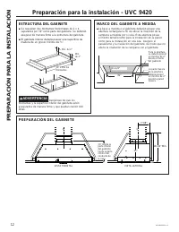
12 49-2000930 Rev. 0 Installation Preparation - UVC 9420 CABINET PREPARATION CL CL 7-5/8” 18-1/2” Min. 15” FRONT VIEW SIDE VIEW CABINET STRUCTURE Ŷ It is required two 2 x 4 horizontal studs separated by 39” as part of the cabinet. They must be firmly secured to the cabinet structure. Ŷ The cabinet b...
Page 13 - Installation Preparation - UVC 9480; INST
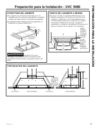
49-2000930 Rev. 0 13 Installation Preparation - UVC 9480 CABINET PREPARATION CL CL 7-5/8” 18-1/2” Min. 15” FRONT VIEW SIDE VIEW Side Panel Side Panel CABINET STRUCTURE Ŷ It is required two 2 x 4 horizontal studs separated by 39” as part of the cabinet. They must be firmly secured to the cabinet stru...
Page 14 - PLAN THE INSTALLATION; REMOVE THE PACKAGING; TOOLS AND MATERIALS REQUIRED (NOT SUPPLIED)
14 49-2000930 Rev. 0 PLAN THE INSTALLATION CAUTION To reduce risk of fire and to properly exhaust air, be sure to duct the air outside – Do not vent exhaust air into spaces within walls or ceilings or into attics, crawl spaces, or garages. WARNING PERSONAL INJURY HAZARD It is recommended that 2 peop...
Page 18 - STEP 1 REMOVE MOTOR
18 49-2000930 Rev. 0 Installation - UVC 9480 INST ALLA TION STEP 1 REMOVE MOTOR ASSEMBLY FROM HOOD CANOPY 1. Remove the metal lid by removing the 3 screws and allowing access to connectors. 2. Disconnect 2 motor cable connectors and 2 capacitor connectors. 3. Remove the 4 screws that attach the moto...
Page 19 - STEP 3 CONNECT ELECTRICAL; STEP 4 INSTALL HOOD CANOPY
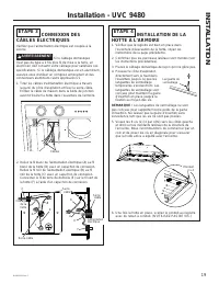
49-2000930 Rev. 0 19 INST ALLA TION Installation - UVC 9480 STEP 3 CONNECT ELECTRICAL CABLES Verify that power is turned off at the source. WARNING If house wiring is not 2-wire with a ground wire, an electrician will need to convert existing wiring to meet these specs. When house wiring is aluminum...
Page 20 - METHOD 1
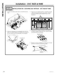
20 49-2000930 Rev. 0 STEP 5 INSTALL BLOWER MOTOR ASSEMBLY - UVC-9420 AND 9480 METHOD 1 1. Lift the motor assembly on the insert canopy. 2. Insert the blower motor assembly tabs in the hood slots and slide it, making sure the 4 tabs are engaged. 3. Tighten the 4 screws (removed earlier) - see Remove ...
Page 22 - STEP 6 FINALIZE INSTALLATION
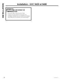
22 49-2000930 Rev. 0 Installation - UVC 9420 and 9480 INST ALLA TION STEP 6 FINALIZE INSTALLATION 1. Insert filters, see the Filters section. 2. Check operation of the lights and blower. Refer to Using the Hood sections for operating instructions.
Page 23 - Before you call for service; Problem; TROUBLESHOOTING TIPS
49-2000930 Rev. 0 23 Troubleshooting tips ... Before you call for service Save time and money! Review the charts on the following pages first and you may not need to call for service. Problem Possible Cause What To Do Fan/Light does not operate when button is turned ON A house fuse may be blown or a...
Page 24 - Notes
Page 26 - LIMITED W; GE Appliances Vented Range Hood Limited Warranty; What GE Appliances will not cover:; a Haier company; Garante en Canadá: MC Commercial
26 49-2000930 Rev. 0 Staple your receipt here. Proof of the original purchase date is needed to obtain service under the warranty . LIMITED W ARRANTY GE Appliances Vented Range Hood Limited Warranty GEAppliances.com All warranty service is provided by our Factory Service Centers, or an authorized Cu...
Page 27 - ACCESSORIES; Looking For Something More?; Accessories; Parts
49-2000930 Rev. 0 27 ACCESSORIES Looking For Something More? GE Appliances offers a variety of accessories to improve your cooking and maintenance experiences! Refer to the Consumer Support page for phone numbers and website information. The following products and more are available: Accessories Par...
Page 28 - Consumer Support
28 49-2000930 Rev. 0 Printed in China Consumer Support CONSUMER SUPPORT Printed in China GE Appliances Website Have a question or need assistance with your appliance? Try the GE Appliances Website 24 hours a day, any day of the year! You can also shop for more great GE Appliances products and take a...
Page 29 - HOTTE À ENCASTREMENT; PERSONNALISÉ; Ventilateur avec QuietBoost
HOTTE À ENCASTREMENT PERSONNALISÉ 49-2000930 Rev. 0 09-22 GEA UVC9420UVC9480 CONSIGNES DE SÉCURITÉ . . . . . . . . 3 UTILISATION DE LA HOTTE Commandes . . . . . . . . . . . . . . . . . . . . . . . . . . . . 5 Chef Connect . . . . . . . . . . . . . . . . . . . . . . . . . . . 6Connexion WI-FI . . . ....
Page 30 - NOUS VOUS REMERCIONS D’ACCUEILLIR GE APPLIANCES CHEZ VOUS; sommes heureux de vous accueillir dans notre famille.
2 49-2000930 Rev. 0 NOUS VOUS REMERCIONS D’ACCUEILLIR GE APPLIANCES CHEZ VOUS Que vous ayez grandi avec GE Appliances ou qu’il s’agisse de votre première acquisition, nous sommes heureux de vous accueillir dans notre famille. Nous sommes fiers du savoir-faire, de l’innovation et de l’esthétique qui ...
Page 31 - VEUILLEZ LIRE TOUTES LES CONSIGNES AVANT D’UTILISER; LISEZ CES INSTRUCTIONS ET RANGEZ-LES SOIGNEUSEMENT
49-2000930 Rev. 0 3 CONSIGNES DE SÉCURITÉ CONSIGNES DE SÉCURITÉ IMPORTANTES VEUILLEZ LIRE TOUTES LES CONSIGNES AVANT D’UTILISER LISEZ CES INSTRUCTIONS ET RANGEZ-LES SOIGNEUSEMENT AVERTISSEMENT POUR RÉDUIRE LE RISQUE D’INCENDIE, DE CHOC ÉLECTRIQUE OU DE BLESSURE CORPORELLE, OBSERVEZ LES DIRECTIVES SU...
Page 32 - Comment retirer le ruban adhésif d’emballage; CONSIGNES DE SÉCURITÉ; MISE AU REBUT ADÉQUATE DE VOTRE ÉLECTROMÉNAGER
4 49-2000930 Rev. 0 Comment retirer le ruban adhésif d’emballage Pour assurer ne pas endommager la finition du produit, la façon la plus sûre pour enlever le ruban adhésif de l’emballage sur les nouveaux appareils consiste à appliquer un détergent à vaisselle liquide à l’aide d’un chiffon doux et à ...
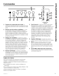
Page 33 - du; Capteur de chaleur
49-2000930 Rev. 0 5 Commandes UTILISA TION DE LA HOTTE : Commandes 1. Panneau de commande de la hotte : Le panneau de commande est situé sur le devant de la hotte. The position and function of each control button are noted below. 2. Bouton marche-arrêt du ventilateur : Il s’agit de l’interrupteur ma...
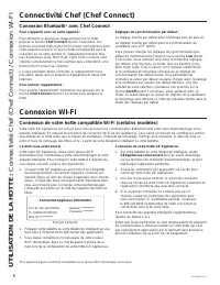
Page 34 - Connexion Bluetooth
6 49-2000930 Rev. 0 UTILISA TION DE LA HOTTE : Connectivité Chef (Chef Connect) / Connexion WI-FI Connexion Bluetooth ® avec Chef Connect Pour s’apparier avec un autre appareil : Pour démarrer le processus d’appariement sur la hotte, pressez le bouton Chef Connect durant 3 secondes. Les boutons Low-...
Page 35 - Plateau d’égouttage de la graisse; Filtre à graisse métallique du déflecteur; Filtres
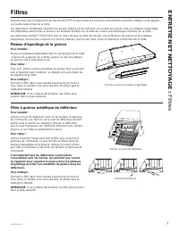
49-2000930 Rev. 0 7 Assurez-vous que le disjoncteur est déclenché (OFF) et que toutes les surfaces sont refroidies avant de nettoyer ou de réparer une partie quelconque de la hotte. Les déflecteurs métalliques canalisent la graisse libérée par les aliments sur la table de cuisson vers les plateaux d...
Page 36 - ENTRETIEN ET NETT; Surfaces en acier inoxydable (certains modèles); Ampoules
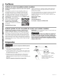
8 49-2000930 Rev. 0 Surfaces peintes et acier inoxydable de couleur noir (certains modèles) N’utilisez pas de tampons à récurer en laine d’acier ni d’autres nettoyants abrasifs car ils rayeront la surface. Nettoyez les surfaces graisseuses de la hotte fréquemment. Pour nettoyer la surface de la hott...
Page 37 - Hotte à encastrement personnalisé; INSTRUCTIONS D’INST; AVANT DE COMMENCER; IMPORTANT —; POUR VOTRE SÉCURITÉ
49-2000930 Rev. 0 9 Instructions d’installation Pour toute question, contactez GE Appliances au 800.561.3344 ou visitez notre site Web sur : electromenagersge.ca au 800.661.1616. Hotte à encastrement personnalisé UVC9420, UVC9480 INSTRUCTIONS D’INST ALLA TION AVANT DE COMMENCER Veuillez lire toutes ...
Page 38 - DIMENSIONS DU PRODUIT; PLANIFICATION PRÉALABLE; Préparation de l'installation
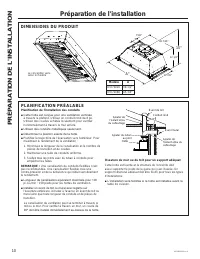
10 49-2000930 Rev. 0 DIMENSIONS DU PRODUIT La conception varie selon le modèle 15" 12 1/2" A" 21 7/8" 7 5/8" 28 7/16" Modèle A UVC9420 39-1/2" UVC9480 45-3/4" PLANIFICATION PRÉALABLE Planification de l’installation des conduits Ŷ&HWWHKRWWHHVWFRQoXHSRXUXQHYHQWLODWL...
Page 39 - DÉGAGEMENTS POUR L’INSTALLATION
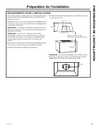
49-2000930 Rev. 0 11 DÉGAGEMENTS POUR L’INSTALLATION Cette hotte doit être installée entre le minimum requis de 30 po et le maximum recommandé de 36 po au-dessus de la surface de cuisson. Ŷ5HSRUWH]YRXVWRXMRXUVDX[LQVWUXFWLRQVGLQVWDOODWLRQGHOD table de cuisson ou de la cuisinière pour les dégagements ...
Page 40 - PRÉPARATION DE L'ENCEINTE; STRUCTURE DE L’ENCEINTE; PRÉPARATION DE L'INSTALLATION
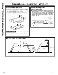
12 49-2000930 Rev. 0 PRÉPARATION DE L'ENCEINTE CL CL 7-5/8” 18-1/2” Min. 15” VUE FRONTALE VUE LATÉRALE STRUCTURE DE L’ENCEINTE Ŷ L’enceinte doit comprendre deux montants horizontaux de 2 x 4 distancés de 39 po. Ces montants doivent être fixés solidement à la structure de l’enceinte. Ŷ La surface en ...
Page 41 - PRÉP
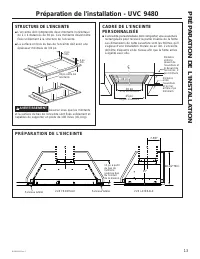
49-2000930 Rev. 0 13 PRÉPARATION DE L'ENCEINTE CL CL 7-5/8” 18-1/2” Min. 15” VUE FRONTALE VUE LATÉRALE STRUCTURE DE L’ENCEINTE Ŷ L’enceinte doit comprendre deux montants horizontaux de 2 x 4 distancés de 39 po. Ces montants doivent être fixés solidement à la structure de l’enceinte. Ŷ La surface en ...
Page 42 - PLANIFIEZ L’INSTALLATION; RETRAIT DE L’EMBALLAGE; PIÈCES FOURNIES
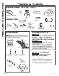
14 49-2000930 Rev. 0 PLANIFIEZ L’INSTALLATION ATTENTION Afin de réduire le risque d’incendie et évacuer l’air correctement, assurez-vous de canaliser l’air à l’extérieur – Ne ventilez pas l’air d’évacuation dans l’espace à l’intérieur des murs, des plafonds ou des combles, ni dans les vides sanitair...
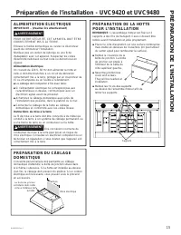
Page 43 - ALIMENTATION ÉLECTRIQUE
49-2000930 Rev. 0 15 PRÉP ARA TION DE L'INST ALLA TION PRÉPARATION DU CÂBLAGE DOMESTIQUE L’enceinte personnalisée doit permettre au câblage domestique d’atteindre la boîte de jonction située dans le schéma ci-dessous. Si la hotte est installée au-dessus d’un îlot, le câblage doit provenir du plafond...
Page 45 - ÉTAPE 3
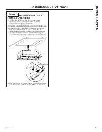
49-2000930 Rev. 0 17 Installation - UVC 9420 INST ALLA TION ÉTAPE 3 INSTALLATION DE LA HOTTE À L’ARMOIRE 1. Vérifiez que le registre est bien en place dans l’ouverture d’évacuation de la hotte, voyez les instructions de la page précédente. 2. Placez le câblage domestique de façon qu'il ne gêne pas.3...
Page 46 - ÉTAPE 1
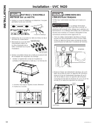
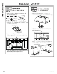
18 49-2000930 Rev. 0 ÉTAPE 2 I NSTALLATION DU REGISTRE ET DU PANNEAU LATÉRAL 1. Installez le registre dans le bas de l’ouverture du ventilateur d’échappement à l’aide des 2 vis fournies (D). a. Assurez-vous que le registre s’ouvre librement. b. Serrez les 2 vis (D). 2. Installez les panneaux latérau...
Page 49 - ÉTAPE 5
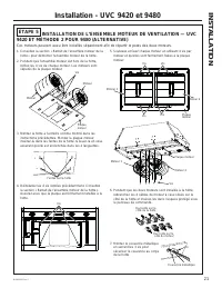
49-2000930 Rev. 0 21 INST ALLA TION Installation - UVC 9420 et 9480 ÉTAPE 5 INSTALLATION DE L’ENSEMBLE MOTEUR DE VENTILATION — UVC 9420 ET MÉTHODE 2 POUR 9480 (ALTERNATIVE) Ces moteurs peuvent aussi être installés séparément afin de répartir le poids des deux moteurs. 1. Consultez la section « Retra...
Page 50 - ÉTAPE 6
22 49-2000930 Rev. 0 Installation - UVC 9420 et 9480 INST ALLA TION ÉTAPE 6 ACHÈVEMENT DE L'INSTALLATION 1. Insérez les filtres, voyez la section Filtres. 2. Vérifiez le fonctionnement de l'éclairage et du ventilateur. Reportez-vous aux sections sur l’utilisation de la hotte pour les instructions de...
Page 51 - Avant d’appeler le service à la clientèle; TRUCS DE DÉP
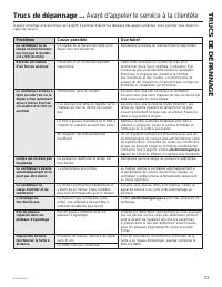
49-2000930 Rev. 0 23 Problème Cause possible Que faire? Le ventilateur ou la lampe ne fonctionnent pas lorsque le bouton est à ON (marche) Un fusible de la maison est grillé ou le disjoncteur est déclenché. Remplacez le fusible ou réenclenchez le disjoncteur. Bruit de circulation d’air fort ou anorm...
Page 52 - GARANTIE LIMITÉE; EXCLUSION DES GARANTIES IMPLICITES; GE; Ce que GE Appliances ne garantit pas :
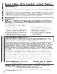
24 49-2000930 Rev. 0 Agrafez ici votre reçu. Une preuve de l’achat original est requise pour l’accès à l‘entretien et aux réparations en vertu de la garantie. Electromenagersge.ca Tout entretien ou réparation en vertu de la garantie est fourni par nos Centres d’entretien et de réparation de l’usine ...
Page 53 - ACCESSOIRES; Vous êtes à la recherche d’autres articles?; Accessoires; Pièces; Articles de nettoyage
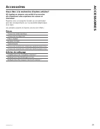
49-2000930 Rev. 0 25 ACCESSOIRES Vous êtes à la recherche d’autres articles? GE Appliances propose une variété d’accessoires afin d’améliorer votre expérience de cuisson et d’entretien! Reportez-vous à la page du Soutien au consommateur pour des renseignements sur l’accessibilité téléphonique et en ...
Page 54 - SOUTIEN AU; Soutien au consommateur
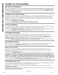
26 49-2000930 Rev. 0 Printed in China SOUTIEN AU CONSOMMA TEUR Imprimé en Chine Soutien au consommateur Site Web de GE Appliances Vous avez une question ou vous avez besoin d’aide pour votre appareil électroménager? Visitez le site Web de GE Appliances 24 heures par jour, tous les jours de l’année! ...
Page 55 - CAMPANAS DE INSERCIÓN; Estándares; Con Extractor QuietBoostTM
Escriba los números de modelo y de serie aquí: Nº de Modelo ____________ Nº de Serie ______________ Los encontrará en una etiqueta dentro de la campana. INFORMACIÓN DE SEGURIDAD . . . . 3 USO DE LA CAMPANA Controles . . . . . . . . . . . . . . . . . . . . . . . . . . . . . . . . . 5Chef Connect . . ...
Page 56 - GRACIAS POR HACER QUE GE APPLIANCES SEA PARTE DE SU HOGAR.; tenerlo en la familia.
2 49-2000930 Rev. 0 GRACIAS POR HACER QUE GE APPLIANCES SEA PARTE DE SU HOGAR. Ya sea que haya crecido usando GE Appliances, o que ésta es su primera vez, nos complace tenerlo en la familia. Sentimos orgullo por el nivel de arte, innovación y diseño de cada uno de los electrodomésticos de GE Applian...
Page 57 - ADVERTENCIA
49-2000930 Rev. 0 3 INFORMACIÓN DE SEGURIDAD INFORMACIÓN IMPORTANTE DE SEGURIDADLEA TODAS LAS INSTRUCCIONES ANTES DE USAR LEA Y GUARDE ESTAS INSTRUCCIONES ADVERTENCIA PARA REDUCIR EL RIESGO DE INCENDIO, DESCARGA ELÉCTRICA O LESIONES A PERSONAS, CUMPLA CON LOS SIGUIENTES PUNTOS: A. Utilice esta unida...
Page 58 - Cómo Retirar la Cinta de Embalaje; INFORMACIÓN DE SEGURIDAD; FORMA ADECUADA DE DESCARTAR SU ELECTRODOMÉSTICO
4 49-2000930 Rev. 0 Cómo Retirar la Cinta de Embalaje Para asegurar que no haya daños sobre el acabado del producto, la forma más segura de retirar el adhesivo de la cinta de embalaje en electrodomésticos nuevos es aplicando un detergente líquido hogareño para lavar platos. Aplique con una tela suav...
Page 59 - Controles; Panel de Control de la Campana Extractora:; Sensor de Calor
49-2000930 Rev. 0 5 Controles USO DE LA CAMP ANA: Controles 1. Panel de Control de la Campana Extractora: El panel de control está ubicado en el frente de la base. La posición y función de cada botón del control aparece escrito debajo. 2. Botón Fan On/Off (Ventilador Encendido/ Apagado): Interruptor...
Page 60 - Conexión de Bluetooth
6 49-2000930 Rev. 0 USO DE LA CAMP ANA: Chef Connect / Conexión Wi-Fi Conexión de Bluetooth ® al Funcionamiento de Chef Connect Para emparejar con otro dispositivo: A fin de iniciar el proceso de emparejamiento, mantenga presionado el botón Chef Connect durante 3 segundos. La luz de fondo de los bot...
Page 61 - Filtros; Bandeja de Goteo de Grasa; Filtro de Grasa Metálico con Deflector
49-2000930 Rev. 0 7 Filtros CUIDADO Y LIMPIEZA: Filtros Asegúrese de que la energía eléctrica esté apagada y que todas las superficies estén frías antes de limpiar o arreglar cualquier pieza de la campana de ventilación. Los deflectores metálicos hacen circular la grasa liberada por las comidas en l...
Page 62 - Lámparas; Superficies; Superficies de acero inoxidable
8 49-2000930 Rev. 0 Lámparas PRECAUCIÓN Espere a que las lámparas se enfríen antes de tocar las mismas. 1. Antes de intentar reemplazar una lámpara, asegúrese de que su interruptor esté apagado. 2. Gire la lámpara en dirección contraria a las agujas del reloj para desbloquear y extraer la misma. Col...
Page 63 - ANTES DE COMENZAR; IMPORTANTE; PARA SU SEGURIDAD; INSTRUCCIONES DE INSTALACIÓN; Campana de Inserción Estándar
49-2000930 Rev. 0 9 Ante cualquier duda, llame a GE Appliances al 800.GE.CARES (800.432.2737) o visite nuestro sitio Web en: GEAppliances.com. ANTES DE COMENZAR Lea estas instrucciones por completo y con detenimiento. • IMPORTANTE — Guarde estas instrucciones para el uso de inspectores locales. • IM...
Page 64 - Preparación para la instalación; DIMENSIONES DEL PRODUCTO; PLANIFICACIÓN PREVIA
10 49-2000930 Rev. 0 Preparación para la instalación PREP ARACIÓN P ARA LA INST ALACIÓN DIMENSIONES DEL PRODUCTO El diseño varía de acuerdo al modelo Modelos A UVC9420 39-1/2" UVC9480 45-3/4" 15" 12 1/2" A" 21 7/8" 7 5/8" 28 7/16" PLANIFICACIÓN PREVIA Planificación pa...
Page 65 - ESPACIOS PARA LA INSTALACIÓN
49-2000930 Rev. 0 11 ESPACIOS PARA LA INSTALACIÓN Esta campana de ventilación deberá ser instalada entre el mínimo requerido de 30” y el máximo recomendado de 36” sobre la superficie de cocción. Ŷ Siempre consulte las instrucciones de instalación de la estufa o cocina en relación a los espacios espe...
Page 66 - Preparación para la instalación - UVC 9420; PREPARACIÓN DEL GABINETE; MARCO DEL GABINETE A MEDIDA; ESTRUCTURA DEL GABINETE
12 49-2000930 Rev. 0 Preparación para la instalación - UVC 9420 PREPARACIÓN DEL GABINETE CL CL 7-5/8” 18-1/2” Min. 15” VISTA FRONTAL VISTA LATERAL MARCO DEL GABINETE A MEDIDA Ŷ La base a medida o el gabinete deberán poseer una abertura rectangular a fin de ubicar la inserción de la campana a medida ...
Page 67 - Preparación para la instalación - UVC 9480
49-2000930 Rev. 0 13 Preparación para la instalación - UVC 9480 PREPARACIÓN DEL GABINETE CL CL 18-1/2” Min. 15” VISTA FRONTAL VISTA LATERAL MARCO DEL GABINETE A MEDIDA Ŷ La base a medida o el gabinete deberán poseer una abertura rectangular a fin de ubicar la inserción de la campana a medida por sí ...
Page 68 - QUITE EL ENVOLTORIO; HERRAMIENTAS Y MATERIALES REQUERIDOS (NO SUMINISTRADOS)
14 49-2000930 Rev. 0 PIEZAS PROVISTAS Ubique las piezas empacadas con la campana. NOTA: Es posible que la valija de herramientas contenga piezas adicionales para realizar una serie de métodos de instalación para diferentes modelos. PLAN DE INSTALACIÓN PRECAUCIÓN A fin de reducir riesgos de incendios...
Page 69 - SUMINISTRO DE ENERGÍA
49-2000930 Rev. 0 15 Preparación para la instalación - UVC9420 y UVC9480 SUMINISTRO DE ENERGÍA IMPORTANTE – (Tenga a bien leer cuidadosamente) ADVERTENCIA PARA SEGURIDAD PERSONAL, ESTE APARATO DEBE CONECTARSE A TIERRA DE MANERA ADECUADA. Quite el fusible o abra el interruptor de circuitos antes de c...
Page 70 - RETIRE EL ENSAMBLE
16 49-2000930 Rev. 0 Instalación - UVC 9420 INST ALACIÓN PASO 1 RETIRE EL ENSAMBLE DEL MOTOR DE LA BASE DE LA CAMPANA 1. Retire la tapa metálica quitando los 3 tornillos y permitiendo el acceso a los conectores. 2. Desconecte los 2 conectores de cables del motor y los 2 conectores de capacitores. 3....
Page 71 - PASO 3 INSTALE LA BASE DE LA
49-2000930 Rev. 0 17 Instalación - UVC 9420 INST ALACIÓN PASO 3 INSTALE LA BASE DE LA CAMPANA EN EL GABINETE 1. Confirme que el regulador se encuentre en su posición en la abertura del extractor de la campana. Para acceder a instrucciones, consulte la página previa. 2. Pliegue el cableado hogareño a...
Page 73 - CONECTE LOS CABLES; INSTALE LA BASE DE LA
49-2000930 Rev. 0 19 Instalación - UVC 9480 INST ALACIÓN PASO 3 CONECTE LOS CABLES ELÉCTRICOS Verifique que la corriente esté apagada en la fuente. ADVERTENCIA Si el cableado hogareño no posee 2 cables con un cable a tierra, un electricista deberá convertir el cableado existente a fin de cumplir con...
Page 75 - PASO 5 INSTALE EL ENSAMBLE DEL MOTOR DEL EXTRACTOR – MÉTODO 2
49-2000930 Rev. 0 21 INST ALACIÓN Instalación - UVC 9420 y 9480 PASO 5 INSTALE EL ENSAMBLE DEL MOTOR DEL EXTRACTOR – MÉTODO 2 (ALTERNATIVO) PARA UVC 9420 Y 9480 Los motores también se podrán instalar de forma separada como ayuda para manejar el peso de los 2 motores. 1. Consulte sobre el Retiro del ...
Page 76 - FINALICE LA INSTALACIÓN
22 49-2000930 Rev. 0 PASO 6 FINALICE LA INSTALACIÓN 1. Controle el funcionamiento de las luces y del calefactor. 2. Finalice los gabinetes estándares. Instalación - UVC 9420 y 9480 INST ALACIÓN
Page 77 - Antes de solicitar el servicio técnico; CONSEJOS P
49-2000930 Rev. 0 23 Problema Causas posibles Qué hacer El Ventilador/ la Luz no funciona cuando el botón está en ON (Encendido) El fusible puede haberse quemado o el interruptor decircuitos puede haber saltado. Cambie los fusibles o reconfigure el interruptor de circuitos. Ruido de flujo de aire mu...
Page 78 - Qué no cubrirá GE Appliances:; GARANTÍA; Garantía Limitada de la Cocina Eléctrica de GE Appliances; EXCLUSIÓN DE GARANTÍAS IMPLÍCITAS
24 49-2000930 Rev. 0 Abroche su recibo aquí. Para acceder al servicio técnico de acuerdo con la garantía deberá contar con la prueba de la fecha original de compra. GEAppliances.com Todo el servicio de garantía es provisto por nuestros Centros de Servicio de Fabricación, o un técnico autorizado de C...
Page 79 - Piezas
49-2000930 Rev. 0 25 ACCESORIOS ¿Busca Algo Más? GE Appliances ofrece una variedad de accesorios para mejorar sus experiencias de cocción y mantenimiento! Para acceder a números telefónicos e información de sitios Web, consulte la página de Soporte para el Consumidor. Estos y otros productos están d...
Page 80 - Soporte para el Consumidor
26 49-2000930 Rev. 0 Impreso en China Soporte para el Consumidor SOPORTE P ARA EL CONSUMIDOR Sitio Web de GE Appliances ¿Desea realizar una consulta o necesita ayuda con su electrodoméstico? ¡Intente a través del Sitio Web de GE Appliances las 24 horas del día, cualquier día del año! Usted también p...


 GE JN327HBB
User Manual
GE JN327HBB
User Manual
 GE JVW5301EJES
User Manual
GE JVW5301EJES
User Manual
 GE JVW5301SJSS
User Manual
GE JVW5301SJSS
User Manual
 GE JVW5361SJSS
User Manual
GE JVW5361SJSS
User Manual
 GE JVX3240SJSS
User Manual
GE JVX3240SJSS
User Manual
 GE JVX3300DJBB
User Manual
GE JVX3300DJBB
User Manual
 GE JVX3300DJWW
User Manual
GE JVX3300DJWW
User Manual
 GE JVX3300SJSS
User Manual
GE JVX3300SJSS
User Manual
 GE JVX5300SJSS
User Manual
GE JVX5300SJSS
User Manual
 GE JVX5305DJBB
User Manual
GE JVX5305DJBB
User Manual
 GE JVX5305DJWW
User Manual
GE JVX5305DJWW
User Manual
 GE JVX5305SJSS
User Manual
GE JVX5305SJSS
User Manual
 GE JVX5360SJSS
User Manual
GE JVX5360SJSS
User Manual
 GE PVX7300SJSS
User Manual
GE PVX7300SJSS
User Manual
 GE PVX7360SJSS
User Manual
GE PVX7360SJSS
User Manual
 GE UVC7300SLSS
User Manual
GE UVC7300SLSS
User Manual
 GE UVC9300SLSS
User Manual
GE UVC9300SLSS
User Manual
 GE UVC9360SLSS
User Manual
GE UVC9360SLSS
User Manual
 GE UVC9420SLSS
User Manual
GE UVC9420SLSS
User Manual
 GE UVD6301DPBB
User Manual
GE UVD6301DPBB
User Manual